🌐 Scene Parameters#
Scene-wide simulation settings (gravity, time step, wind, air density, frame count, CG tolerances) all live in one place: the Scene Configuration panel in the 3D viewport’s sidebar.
Scene Configuration Panel#
Open the sidebar (N) in the 3D viewport and switch to the add-on’s tab.
The Scene Configuration panel is the third panel, below Backend
Communicator and Solver; everything in it is scoped to the whole
scene rather than a single object group.
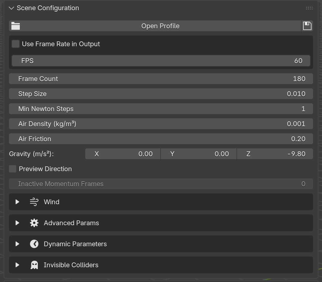
Default layout of the Scene Configuration panel. Top-down: the
Open Profile row (no profile loaded yet), the basic parameters
block, and the five collapsible sub-section headers. Grayed rows
(like Inactive Momentum Frames here) are gated on scene contents.#
The top row is the scene profile row. If no profile is loaded you see an Open Profile button plus a small save icon; once a profile is open the row collapses into a dropdown (the profile selector) with four icon buttons on the right: Open, Clear, Reload, and Save (identical layout to the per-group material profile row). Opening a profile reads its TOML payload into the scene parameters the profile covers, replaces the legacy dynamic-parameter entries, and replaces invisible colliders. Clear drops the association without touching current values. Reload re-reads the file from disk. Save writes the current scene parameters, dynamic-parameter block, and invisible-collider block back out to the file.
Important
The scene-profile TOML file is authored through the Save icon, not by
hand. Configure the Scene Configuration panel (basic parameters,
Wind, Invisible Colliders, Linear System Solver, Advanced Params) the
way you want it, then click the Save icon on the profile row: the
add-on creates a new .toml on the first save and overwrites the
currently selected entry on later saves. The TOML layout shown further
down is for inspection only; the intended workflow is always UI → Save.
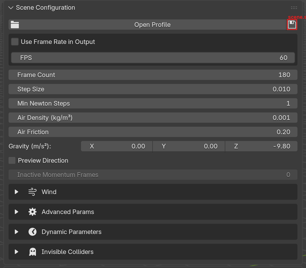
The Save icon (floppy disk, highlighted in red) at the top-right of
the Scene Configuration profile row. Clicking it writes the scene
parameters, the wind block, the linear-solver and advanced settings, the
legacy dynamic-parameter block and the invisible colliders out to the
.toml file. World Scaling, Friction Mode, Save State on
Finish, Keep Saved States and the Save Checkpoints list are
not part of a scene profile (Auto Save and its interval are), and
neither are keyframes drawn on a slider; those stay on the .blend.#
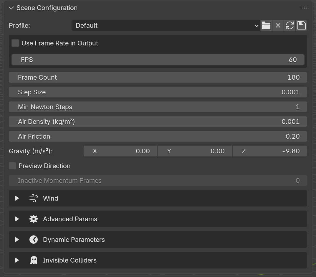
With a scene profile loaded, the top row collapses into a Profile dropdown with four icons on the right: Open, Clear, Reload, Save. Switching entries in the dropdown applies that preset to the scene (overwriting scene parameters, dynamic parameters, and invisible colliders).#
Below the profile row, the panel lays out the basic parameters one per line: FPS (inside a small box, with a checkbox to drive it from Blender’s render FPS instead, and a Time Scale slider that re-interprets how much simulated time one frame covers), a Starting Frame box (with its own checkbox to take the start frame from the scene), Frame Count, Step Size, Min Newton Steps, Air Density, Air Friction, World Scaling, Gravity (a 3-component vector), a Preview Direction toggle (viewport arrow), and an Inactive Momentum Frames row that is grayed-out unless the scene contains at least one Shell group.
Below the basics, five collapsible sub-sections hang off the panel, in this order: Save and Checkpoints, Wind, Invisible Colliders, Linear System Solver, and Advanced Params. Each has a disclosure triangle on its header row and toggles open/closed independently:
Save and Checkpoints: save-on-finish, the auto-save interval and retention, and the explicit checkpoint-frame list. Covered below in Save and Checkpoints.
Wind: wind direction vector, preview toggle, wind strength.
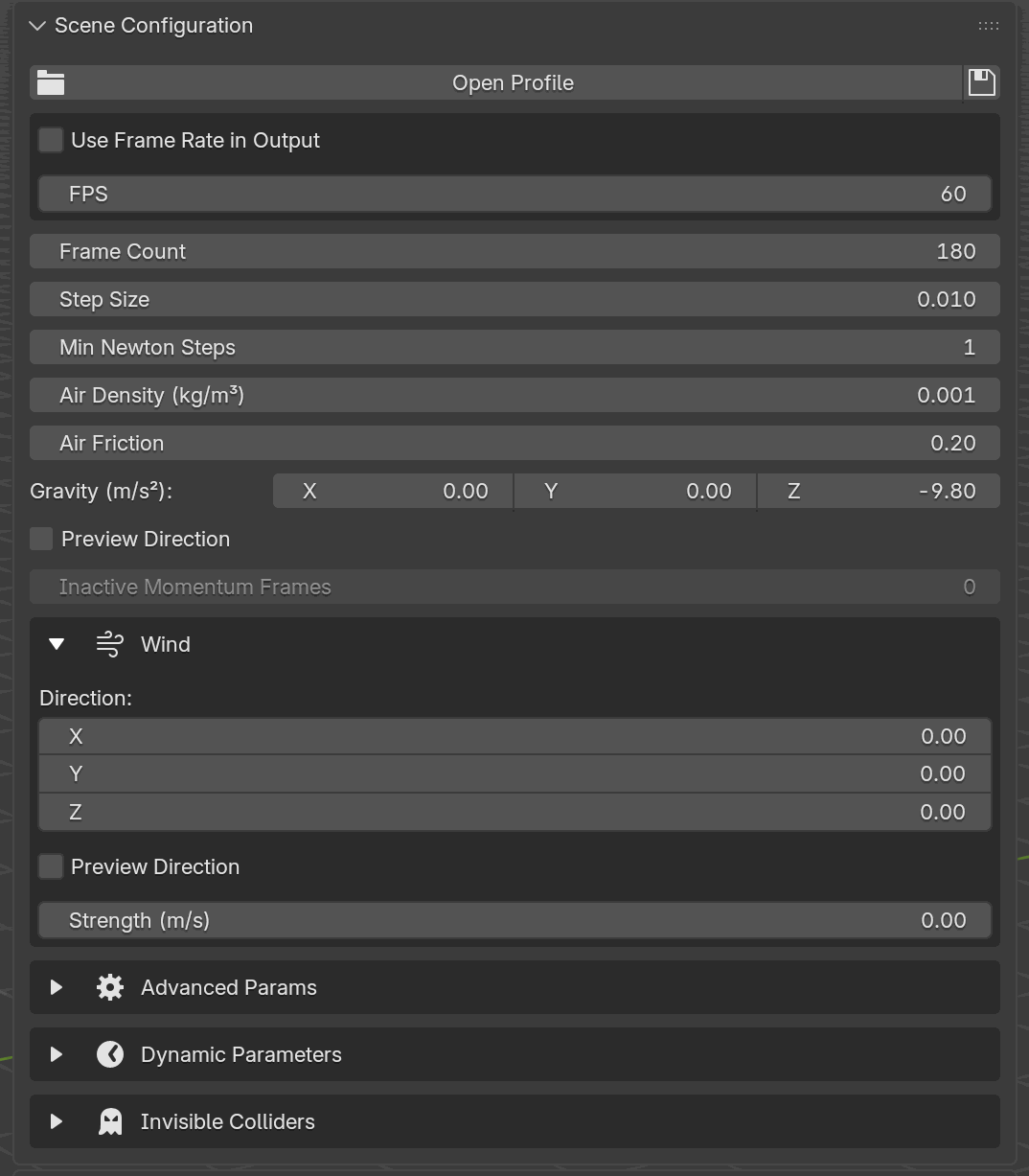
With the Wind disclosure triangle open, the sub-section reveals a Direction XYZ field, a Preview Direction viewport toggle, and a Strength (m/s) scalar. Encoding combines direction × strength, so a zero-direction vector disables wind regardless of the strength value.#
Invisible Colliders: walls and spheres with their own keyframe lists. Covered separately in Invisible Colliders.
Linear System Solver: CG max iter, CG tol, the preconditioner choice, and — only while Schwarz is selected — Schwarz Levels.
Advanced Params: contact NNZ, vertex air damp, CCD line-search max t, constraint ghat, include-face-mass, friction-mode, and disable-contact toggles.
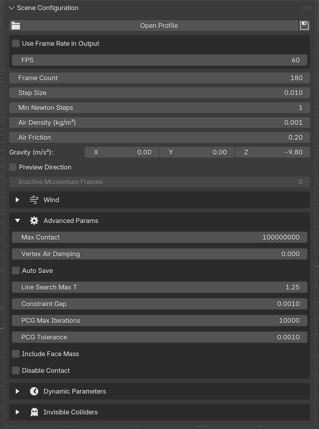
Advanced Params exposes the tuning knobs most users never need to touch: contact-matrix capacity (Max Contact), per-vertex air drag, CCD line-search bounds, the barrier gap, the friction-combination mode, and two debugging toggles. Raise Max Contact only when the solver reports overflow. The PCG iteration cap, its tolerance and the preconditioner choice are one box up in Linear System Solver, and Auto Save is in Save and Checkpoints.#
Keyframed gravity, wind, air density, air friction, vertex air damp, step size and inactive-momentum frames are no longer a sub-section of their own: each is keyframed on its own slider. See Dynamic Parameters.
Only the sub-section headers are visible when collapsed; click the triangle on any of them to expand.
Basic#
UI label |
Python / TOML key |
Default |
Description |
|---|---|---|---|
Frame Count |
|
180 |
Simulation length in frames. Minimum 10. |
FPS |
|
60 |
FPS used to convert frames to seconds at encode time. Minimum 1, soft max 240. |
Take FPS from Scene |
|
|
Run at Blender’s own frame rate instead of the FPS field. |
Time Scale |
|
1.0 |
Playback speed of the Blender animation in simulated time. |
Starting Frame |
|
1 |
Blender frame the first output frame lands on; simulated time zero. Minimum 0. |
Take Starting Frame from Scene |
|
|
Start at the Blender scene’s start frame instead of the field. |
Step Size |
|
0.01 |
Solver sub-step Δt, in seconds. Range 0.001 – 0.01. |
Min Newton Steps |
|
1 |
Minimum Newton iterations per step. 1 – 64. |
Air Density (kg/m³) |
|
0.001 |
Air density, kg/m³. Range 0 – 0.01. |
Air Friction |
|
0.2 |
Tangential-to-normal air drag ratio, 0 – 1 (see below). |
World Scaling |
|
1.0 |
Uniform scale applied to all geometry before simulating; the result is scaled back, so the scene keeps its authored size. Range 0.001 – 1000 (see below). |
Gravity (m/s²) |
|
(0, 0, -9.8) |
Gravity vector, m/s² (Z-up Blender frame). |
Preview Direction (gravity) |
|
|
Draw the gravity-direction arrow overlay in the viewport. Overlay-only. |
Inactive Momentum Frames |
|
0 |
Frames over which shell momentum is ignored at startup (0 – 600). |
Inactive Momentum Frames is only honored when the scene contains at least one Shell group; otherwise the UI disables the row.
Air Friction#
At every shell vertex, the solver accumulates an air-damping force
that resists motion relative to the wind. The move (x¹ - x⁰) - Δt·w
(current minus previous position, minus the wind displacement over
one step) is split by the vertex normal into a normal component
and a tangential component, and the two are weighted differently
in the damping energy:
Normal drag is always on with coefficient
1. Pushing a shell face into or out of the air is always resisted.Tangential drag is scaled by Air Friction. At
0, air offers no sideways resistance, so a shell can slide edgewise through still air unopposed. At1, tangential and normal drag are equal in magnitude. The default0.2gives air a little “grip” on the fabric without over-damping swings.
The per-vertex air-damping force is then scaled by the vertex’s
associated area and by Air Density before being added to the
Newton solve. A side-effect of that last multiplication: at
air_density = 0 there is no shell air damping at all, regardless of
Air Friction.
Vertex Air Damping (under Advanced) is a separate, isotropic per-vertex damper applied to every vertex in the scene, with no area or air-density weighting and no directional split. Use it when you need to calm a rod or a particle-heavy scene that Air Friction does not reach.
Both Air Friction and Vertex Air Damping are keyframeable; see Dynamic Parameters.
World Scaling#
World Scaling multiplies all geometry by this factor on the way into
the solver and divides the simulated result back out on the way home, so
the scene keeps the size you authored it at. Use it when a scene is
modeled at a size it does not represent: at 0.1 a 15 m mesh is
simulated as if it were 1.5 m.
Everything with units of length scales with the geometry: initial
velocities, keyframed translations, invisible-sphere radii, and each
group’s Contact Gap and Contact Offset. So a contact that just
touches at 1.0 still just touches at any other setting. Gravity and the
scene-level Constraint Gap are absolute and are left alone, which is
what the control is for: holding gravity fixed while the geometry moves
to another scale is what makes the scene behave as the size it
represents.
A Rod group’s Bend Stiffness is measured against a 1 cm reference
segment in solver units, that is, after World Scaling has been
applied. At the default 1.0 the reference is simply the segment length
as drawn in Blender. See Material Parameters.
Wind#
UI label |
Python / TOML key |
Default |
Description |
|---|---|---|---|
Wind (disclosure) |
|
|
Whether the Wind sub-section is expanded. |
Direction |
|
(0, 0, 0) |
Wind direction (normalized at encode time). |
Preview Direction |
|
|
Draw the wind-direction arrow overlay in the viewport. Overlay-only. |
Strength (m/s) |
|
0.0 |
Wind speed, m/s. Range 0 – 1000. |
The encoder combines the two into a single direction × strength vector
before sending. If Direction is (0, 0, 0), no wind is applied
regardless of Strength (m/s).
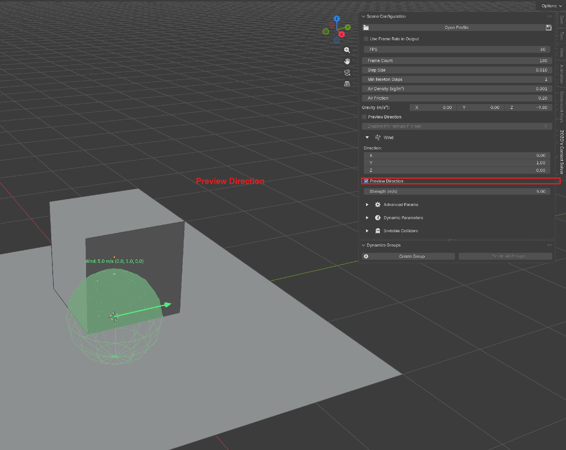
A live example of the Wind fields. With Direction = (0, 1, 0) and
Strength = 5.0 m/s, the encoder ships direction × strength = (0, 5, 0) to the solver. Turning Preview Direction on draws the green
wind-arrow overlay (and a translucent sphere sized to a fixed fraction
of the current view distance, for scale) so you can judge the wind field
relative to scene geometry without running a simulation. It is the
arrow’s length that tracks the strength, up to a cap. The viewport label
echoes the magnitude and normalized direction live.#
Advanced#
The panel splits these across two boxes. Linear System Solver holds PCG Max Iterations, PCG Tolerance, Preconditioner and Schwarz Levels; Advanced Params holds the rest.
UI label |
Python / TOML key |
Default |
Description |
|---|---|---|---|
Max Contact |
|
100 000 000 |
Capacity of the contact sparse matrix (non-zero entries). |
Vertex Air Damping |
|
0.0 |
Per-vertex isotropic air damping, 0 – 1. |
Line Search Max T |
|
1.25 |
CCD line-search maximum step factor. Range 0.1 – 10. |
Constraint Gap |
|
0.001 |
Barrier gap distance. Range 0.0001 – 0.1. |
PCG Max Iterations |
|
10 000 |
Max iterations for the PCG linear solver. 100 – 100 000. |
PCG Tolerance |
|
0.001 |
PCG relative tolerance. 0.00001 – 0.1. |
Preconditioner |
|
|
Preconditioner used by the PCG linear solver. Choices: |
Schwarz Levels |
|
|
Number of additive Schwarz levels (used only when Preconditioner is |
Include Face Mass |
|
|
Fold shell face mass into attached solids. |
Friction Mode |
|
|
How to combine the two contacting objects’ friction coefficients. Choices: |
Disable Contact |
|
|
Turn off contact detection entirely (debugging / ablation). |
Raise PCG Max Iterations (and lower PCG Tolerance) for stiff systems that fail to converge. Raise Max Contact only if the solver reports a contact-matrix overflow; it’s an upper bound, not a target.
Preconditioner#
The Preconditioner selects how the PCG linear solver is accelerated. Both choices produce the same result; they differ only in how quickly the solver converges and, with it, the wall-clock cost per frame.
Block Jacobi (the default) treats each vertex on its own. Each PCG iteration is cheap, so it is fast in practice, and it keeps a small, steady memory footprint even on scenes with very heavy contact.
Schwarz groups nearby vertices and solves each group together. On scenes that mix stiff and soft materials it can converge in fewer PCG iterations, but each iteration costs more and it uses more memory, which on scenes with very heavy contact can be enough to run out of memory.
If you are unsure, leave it on Block Jacobi. Switch to Schwarz only if a scene that mixes stiff and soft materials is slow to converge and you have memory to spare.
Schwarz Levels#
When the Preconditioner is set to Schwarz, the Schwarz Levels control picks how many additive levels the preconditioner uses. It has no effect on Block Jacobi, and the row is shown only while Schwarz is selected.
Level 2 (the default) adds a coarse correction over the connectivity partition on top of the per-aggregate solve. On stiff multibody contact this lowers the worst-case PCG iteration count, so it is the better all-around choice.
Level 1 uses a single-level additive aggregate-Schwarz smoother only. It is cheaper to set up per iteration but can take more PCG iterations on stiff or mixed scenes.
Leave it on Level 2 unless you are profiling and want to compare against the single-level smoother.
Save and Checkpoints#
A long simulation can save its state along the way so you can resume it later instead of starting over. These settings control when those saves happen and how many are kept.
UI label |
Python / TOML key |
Default |
Description |
|---|---|---|---|
Save State on Finish |
|
|
Save the state on the final frame before the solver exits, so the finished result stays resumable even when Auto Save is off. |
Auto Save |
|
|
Save the state periodically while the simulation runs. |
Auto Save Interval |
|
10 |
How often to auto-save, in frames. Minimum 1. |
Keep Saved States |
|
0 |
How many auto-saved states to keep. |
Save Checkpoints |
|
(empty) |
An explicit list of frames at which to save a resumable state. |
Auto Save writes a fresh state every Auto Save Interval frames.
With Keep Saved States at its default 0, every one of those states
is kept, so you can resume from any of them later. Set it to a positive
number to keep only that many of the most recent states; older ones are
discarded as new ones are written. Keep it at 0 if you want the option
to resume from earlier frames.
Save Checkpoints lets you pick specific frames to save, in addition to (or instead of) the regular Auto Save schedule. Add the frames you care about to the list and the solver writes a resumable state at each one. The list is empty by default.
The Resume dialog offers exactly the frames that have been saved. Auto-saved frames, the on-finish save, and your explicit Save Checkpoints all show up there; pick one to continue the simulation from that point without re-sending geometry or rebuilding.
Previewing Direction#
Both Gravity and Wind have a Preview Direction toggle next to their vector fields. Turning it on draws an arrow (and a translucent sphere for scale) in the 3D viewport showing the current direction (and for wind, the magnitude) so you can judge the setup before running a simulation.
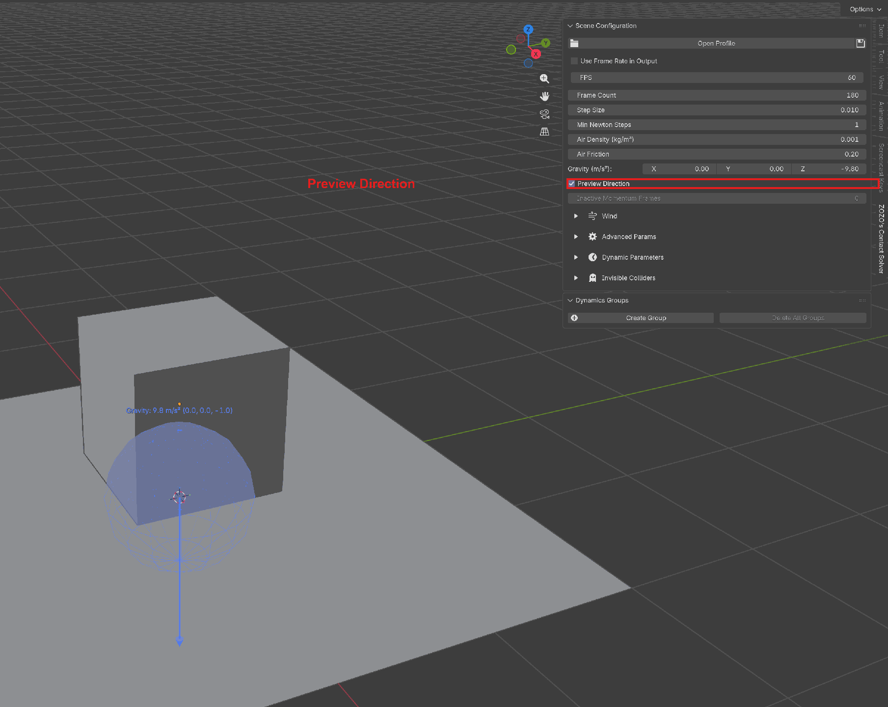
With Preview Direction enabled next to the gravity vector, a blue arrow is drawn in the 3D viewport pointing in the gravity direction. The text label echoes the magnitude and normalized direction. Toggle it off to declutter the viewport.#
Wind preview with direction (0, 1, 0) and strength 5.0 m/s. The
green arrow’s length scales with the wind strength, so you can see at a
glance how strong the wind field is relative to the scene geometry.#
The Preview Direction toggles (one for gravity, one for wind) are also exposed to Python, so you can flip them from a script. They are purely viewport overlays; they never affect the simulation.
What Update Params Does#
On the Solver panel, Update Params on Remote re-encodes the parameters (scene block, per-group block, pin config, merge pairs, dynamic parameters, invisible colliders) and ships them to the solver, then triggers a rebuild. Geometry is not resent; the mesh buffers on the server are preserved. Use this when you want to tweak material parameters, gravity, or dynamic keyframes without paying the full transfer cost.
Topology changes (adding or removing vertices, edges, or faces) still require a full Transfer, because the mesh hash changes.
Scene Profiles#
A scene profile is a named set of scene parameters saved to a TOML file with the Save icon. A file can hold any number of presets; for example:
Preset |
Highlights |
|---|---|
|
step 0.001 s, 180 frames at 60 FPS, gravity (0, 0, -9.8). |
|
Same as |
|
step 0.001 s (the minimum), 360 frames, |
|
600 frames at 120 FPS. Step size stays at 0.001 s. |
|
|
Note
The Default preset above is just a profile name in this example, not
the addon’s new-scene default. These presets deliberately tighten step_size
to 0.001 s for the more demanding example setups; a fresh Blender scene
still starts at the addon default of 0.01 s (see the Basic table).
Unlike material profiles, scene profiles also capture dynamic parameters and invisible colliders. Applying the profile clears existing dynamic parameters and invisible colliders first, then rebuilds them from the TOML entries.
The example below is shown so you can read or diff an existing file; it is produced by clicking Save, not written by hand. Tweak the scene in the panel and click Save again rather than editing TOML directly.
Example excerpt:
[Default]
step_size = 0.001
min_newton_steps = 1
air_density = 0.001
air_friction = 0.2
gravity = [0.0, 0.0, -9.8]
frame_count = 180
frame_rate = 60
wind_direction = [0.0, 1.0, 0.0]
wind_strength = 0.0
contact_nnz = 100000000
cg_max_iter = 10000
cg_tol = 0.001

[[Default.dyn_params]]
param_type = "WIND"

[[Default.dyn_params.keyframes]]
frame = 1

[[Default.dyn_params.keyframes]]
frame = 40
use_hold = true

[[Default.dyn_params.keyframes]]
frame = 60
wind_direction_value = [0.0, 1.0, 0.0]
wind_strength_value = 5.0

[[Default.colliders]]
collider_type = "SPHERE"
name = "Floor Bowl"
position = [0.0, 0.0, 0.0]
radius = 0.98
hemisphere = true
invert = true
contact_gap = 0.001
friction = 0.0

[[Default.colliders.keyframes]]
frame = 1
Note
Scene profiles do not touch object groups, pins, or merge pairs. Those live on per-group material profiles and on the scene file itself.
Blender Python API#
The same workflow is available from Python. The settings are reachable
through solver.param. Assignments are immediate; they don’t require a
transfer, but do require update_params() before the solver actually
sees the new values on the next run.
from bl_ext.user_default.ppf_contact_solver.ops.api import solver

solver.param.gravity = (0, 0, -9.8)
solver.param.frame_count = 180
solver.param.step_size = 0.001

# Ship the new values to the remote without re-sending geometry.
solver.update_params()
Under the hood
FPS from the Blender scene
The checkbox in the FPS box (use_scene_fps, labeled Take FPS
from Scene) runs the simulation at Blender’s own frame rate instead of
the FPS field. While it is on, the panel replaces the field with an
FPS (from Scene) readout, because frame_rate keeps whatever value
it last held: the rate the solver runs at is the one on that readout,
not the one in the field. Over MCP the same number comes back as
effective_fps.
Scene profile shape
A scene profile TOML entry has a flat block of the scene-parameter keys
at the top, followed by [[<Profile>.dyn_params]] arrays describing
keyframed parameters and [[<Profile>.colliders]] arrays describing
walls and spheres.
Solver payload keys
At transfer time the scene parameters are sent under solver-side names:
dt, min-newton-steps, air-density, air-friction, gravity[3], wind[3],
frames, fps, csrmat-max-nnz, constraint-ghat, cg-max-iter, cg-tol,
include-face-mass, disable-contact, inactive-momentum,
line-search-max-t, auto-save, ...
Update Params on Remote reships this payload without re-encoding geometry.