👻 Invisible Colliders
Invisible colliders are parametric collision boundaries that constrain the simulation without being part of the Blender scene. Use them for ground planes, containment volumes, bowls, cages, and quick test rigs you do not want cluttering the viewport or render.
They are purely a solver construct: they have no mesh, no modifier, and are not affected by the scene’s render or viewport visibility. They are persisted as part of the scene profile.
Adding a Collider
Open the sidebar (
N) in the 3D viewport and switch to the add-on tab.In the Scene Configuration panel, scroll to the Invisible Colliders sub-panel and click the disclosure triangle to expand it.
Click Add (the button with the plus icon). A small dropdown offers two options, Wall and Sphere. Pick one.
A new entry appears in the list above the Add / Remove row, named
Wall 1,Sphere 1,Wall 2,Sphere 2, … by number of existing entries of that type.Every new collider gets a fixed frame-1 keyframe automatically; it reads from the base properties and cannot be deleted.
Selecting a collider in the list opens a properties box just below it with inline fields for the current collider. What you see depends on the collider type:
Wall: Name, Position, Normal, Contact Gap, Friction, Thickness, and an Active Duration toggle (expands to a duration field when on).
Sphere: Name, Position, Radius, side-by-side Invert and Hemisphere checkboxes, then the same Contact Gap, Friction, Thickness, Active Duration rows as Wall.
To remove a collider, select it in the list and click the Remove button to the right of Add. Remove is grayed out when nothing is selected.
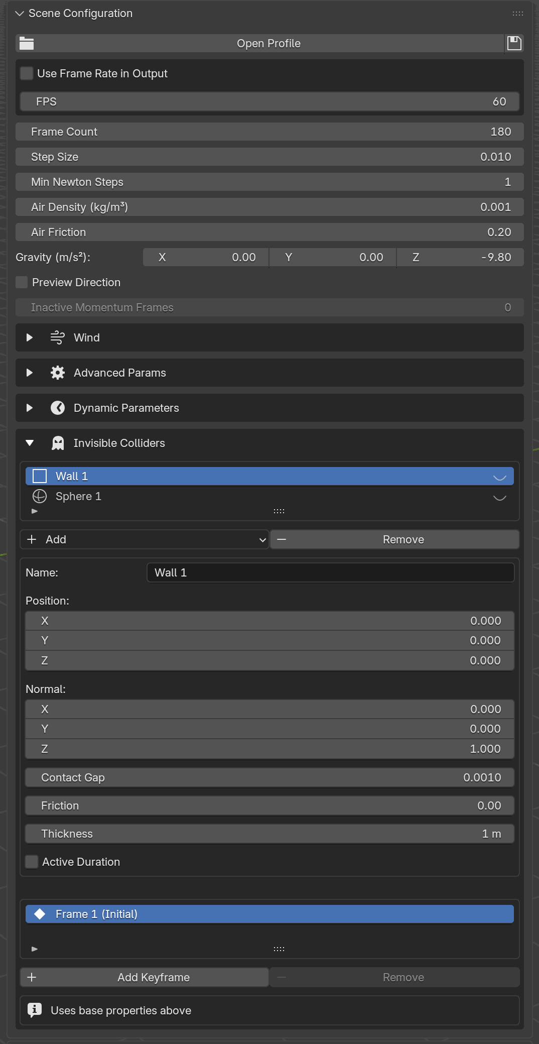
The Invisible Colliders sub-panel with two entries (Wall 1 and
Sphere 1) and the properties box open for the selected wall
(Name, Position, Normal, Contact Gap, Friction, Thickness, Active
Duration). Below, the keyframe list shows the auto-generated frame-1
Initial keyframe.
Preview Overlay
Because an invisible collider has no mesh, the only way to see where it sits, and crucially which side it pushes against, is the Preview overlay. Each row in the collider list carries a small eye icon on the right. The preview is off by default (closed-eye icon): the wall or sphere exists in the solver but nothing draws in the viewport. Click the icon to flip it to the open-eye state and the collider draws directly in the 3D viewport, updated live as you edit Position, Normal, Radius, or as the timeline advances through keyframes. Click the open eye again to hide the preview.
Previews are per-collider, so you can isolate one while keeping others hidden. They also respect the Active Duration cutoff: once the current frame passes the end frame the overlay disappears, mirroring what the solver does.
Interpreting the Arrows
The overlay always draws one or more normal arrows pointing in the direction the collider pushes geometry away from. Read them as “dynamic vertices live on the arrow side”:

The five variants at a glance. In every panel the blue (outward) or purple (inward) arrow points toward the free side, where dynamic geometry is allowed to live. The shaded fill marks the solid side (anything that lands there is projected back across the surface), and dashed outlines mean the surface continues to infinity.
Wall. A single arrow sticks out of the plane along its Normal. Points on the arrow side are free; points on the opposite side get projected back across the plane. The solid grid shows a small patch of the plane at Position, and the faint dashed outlines expanding outward are a reminder that the plane is infinite; the wall extends well past the rendered patch.
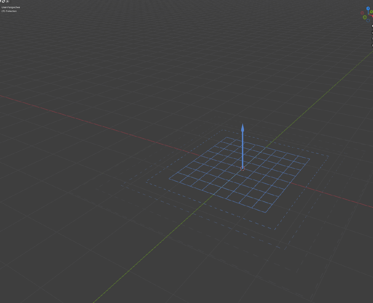
A floor wall (
Position = (0, 0, 0),Normal = (0, 0, 1)). The arrow tells you dynamic geometry stays on the +Z side.¶Sphere. Six arrows appear at the cardinal surface points (±X, ±Y, ±Z for a full sphere; no +Z for a hemisphere). Their direction encodes the two shape flags:
Default sphere: arrows point outward. Geometry stays outside the ball.
Invert ✓: arrows flip to point inward, toward the center. The sphere becomes a containment volume; geometry stays inside.
Hemisphere ✓: the wireframe becomes the lower half plus a cylinder extending upward from the equator (the solver treats the region above the equator as an infinite capsule). Combine with Invert for a bowl that catches falling objects from above.
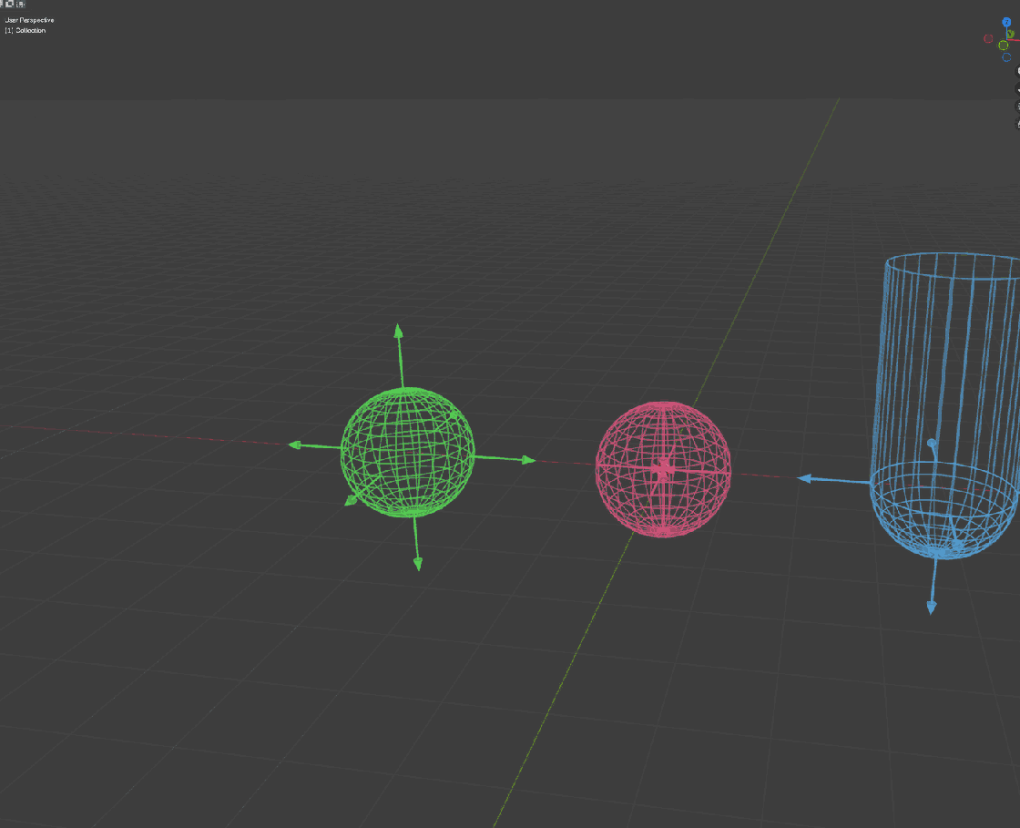
Left to right: a default sphere (objects stay outside, arrows point away from the center), an inverted sphere (containment: objects stay inside; arrows point toward the center and are mostly hidden inside the wireframe), and a hemisphere (lower half + cylindrical extension upward).
Each collider is given a distinct hue: walls start blue, spheres start green, and subsequent entries rotate through the hue wheel, so several overlays stay readable side-by-side.
Keyframe Animation
Colliders animate through their own per-collider keyframe list below the properties box, not through Blender fcurves. Each keyframe stores a frame number plus the values that change at that frame (Position for both, Radius for spheres).
To animate the selected collider:
With the collider selected, scrub the timeline to the frame you want.
Click Add Keyframe. A new entry is appended to the keyframe UIList, seeded from the collider’s current values, on the current scene frame. Duplicate frames are rejected.
Select the new keyframe in the list. A keyframe-details box appears below with Frame, Hold, and (when Hold is off) the keyframed value rows (Position, plus Radius for spheres).
Adjust values inline. To delete, select the keyframe and click Remove.
The first keyframe in the list is badged Initial. It is frozen to frame 1 and shows the message “Uses base properties above” instead of value rows. It reads whatever is currently in the properties box and cannot be removed; its Remove button stays disabled.
Turning Hold on for any later keyframe makes that frame hold the previous keyframe’s value, producing a step function. Useful for “stay put until frame 60, then jump to the next state” patterns: add a Hold keyframe on 60 and a value keyframe on 61.
Example: Shrink a Sphere Starting at Frame 60
A sphere that keeps radius = 1.0 until frame 60, then shrinks to
0.5 over the next 60 frames (reaching 0.5 at frame 120):
Add a Sphere collider and set its base
Position = (0, 0, 0)andRadius = 1.0in the properties box.Scrub to frame 60, click Add Keyframe, select the new
Frame 60row, and turn Hold on. No value rows are needed; the encoder will re-emit the previous keyframe’s value (1.0) at this frame.Scrub to frame 120, click Add Keyframe, select the new
Frame 120row, leave Hold off, and setRadius = 0.5.

What the sphere actually looks like at each of those frames. The
first three snapshots are identical in size (that’s the Hold
plateau doing its job), and the last two show the linear ramp
between Frame 60 and Frame 120. The faint dashed ring at
the Frame 120 position marks the original R = 1.0 so you can
eyeball how much it has shrunk.

The three keyframes above, plotted. The solid blue line is the
resulting radius curve: flat until frame 60 (the Hold keyframe
re-emits the previous value of 1.0), then a linear ramp down to
0.5 at frame 120. The dashed gray line is what the sphere would
do if you dropped the Hold at frame 60: a straight interpolation
from 1.0 to 0.5 spread over all 119 frames, so shrinking would
start immediately at frame 1.
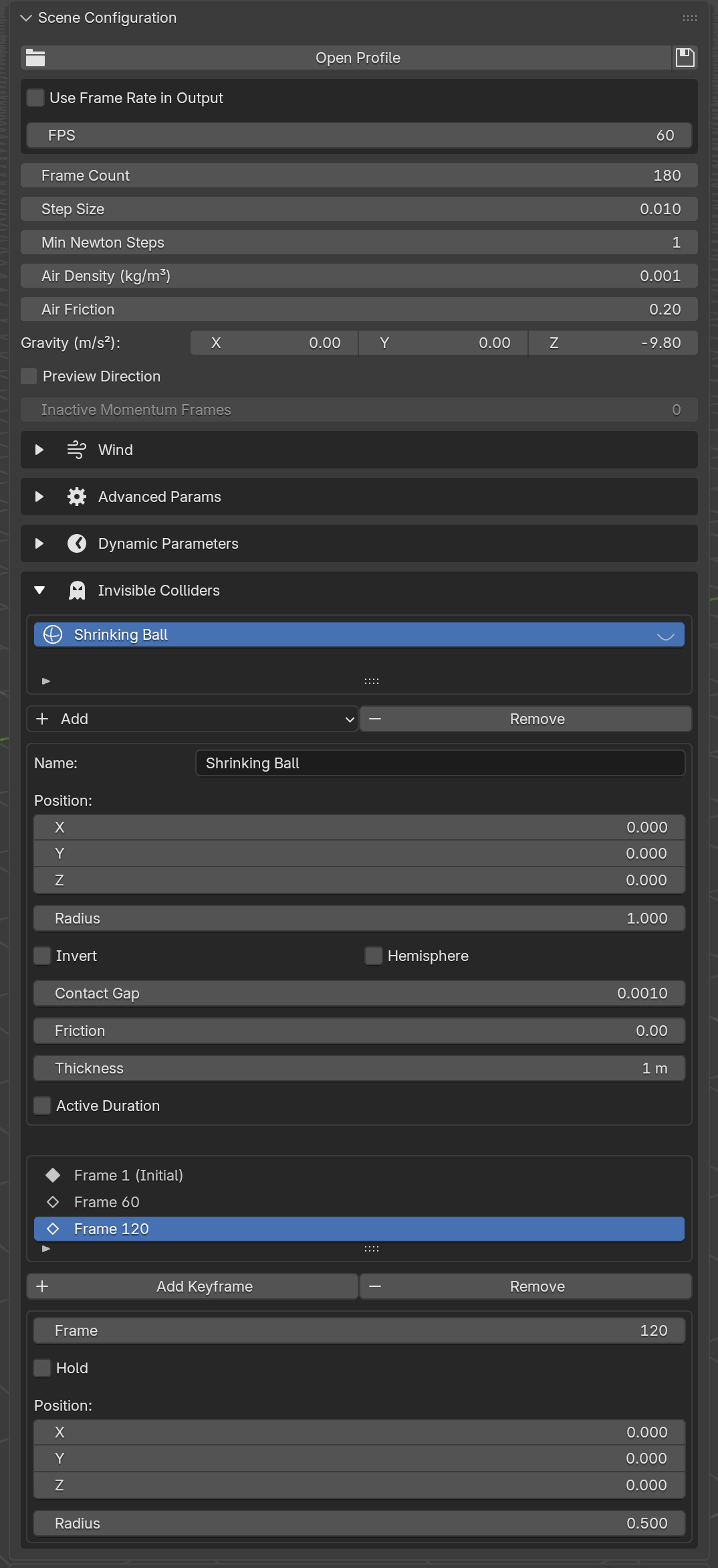
The resulting sub-panel. The sphere has three keyframes: Frame 1 (Initial), Frame 60 (Hold), and Frame 120 (Radius → 0.500, currently selected). Because frame 60 holds the previous radius (1.0), the solver keeps the sphere at 1.0 through frame 60 and then linearly interpolates from 1.0 to 0.5 across frames 60-120.
Without the Hold at frame 60 the solver would linearly interpolate radius from 1.0 (frame 1) to 0.5 (frame 120) across all 119 frames, so the sphere would start shrinking immediately at frame 1 instead of holding its initial size until frame 60.
Types and Options
Type |
Shape |
Extra options |
|---|---|---|
Wall |
Infinite plane at Position with outward Normal. |
N/A |
Sphere |
Sphere at Position with Radius. |
Invert, Hemisphere |
A wall pushes simulation geometry onto the normal-facing side of the plane.
A sphere, by default, collides from the outside: objects stay outside the ball. Turning Invert on flips that, so objects stay inside the ball (a containment volume). Turning Hemisphere on leaves the top half open (a bowl). Both flags can be combined.
Both collider types also carry the usual contact settings:
UI label |
Python / TOML key |
Meaning |
|---|---|---|
Contact Gap |
|
Barrier gap maintained between the collider and dynamic geometry. |
Friction |
|
Tangential friction coefficient. |
Saving with a Scene Profile
Invisible colliders and their keyframes are written into the scene profile TOML alongside dynamic parameters. See Scene Parameters. They are not stored per material profile or per group.
The scene-profile .toml is generated by clicking the Save icon on
the Scene Configuration profile row, not by editing TOML by hand. Add
and tune colliders in this panel and then save from Scene Configuration
to persist them.
Blender Python API
The same workflow is available from Python:
from bl_ext.user_default.ppf_contact_solver.ops.api import solver

# A floor (wall facing up) with 0.5 friction.
floor = solver.add_wall([0, 0, 0], [0, 0, 1])
floor.param.friction = 0.5

# A bowl centered at origin: inside-collision hemisphere sphere.
bowl = solver.add_sphere([0, 0, 0], 0.98).invert().hemisphere()
bowl.param.friction = 0.3

# Animated sphere: hold radius=1.0 until frame 60, then jump to 0.5.
solver.add_sphere([0, 0, 0], 1.0).time(60).hold().time(61).radius(0.5)

# Animated wall: slide 1 m along +Y between frames 30 and 90.
(solver.add_wall([0, 0, 0], [0, 1, 0])
       .time(30).hold()
       .time(90).move_to([0, 1, 0]))

# Start over.
solver.clear_invisible_colliders()
Both builders are chainable. time(frame) advances the keyframe cursor
(frames must strictly increase) and hold() emits a hold keyframe.
The value-keyframe methods differ by collider type:
Wall exposes
move_to(position)(absolute world-space position) andmove_by(delta)(offset from the previous keyframe). Walls do not have a radius, andtransform_tois sphere-only.Sphere exposes
move_to(position),radius(r)(keyframe a new radius), andtransform_to(position, radius)(keyframe both together). Sphere builders do not exposemove_by.
param.contact_gap and param.friction set the collider’s per-contact
values without keyframing them.