📌 Pins and Operations
A pin is a named set of vertices on an object that the add-on has marked as a constraint target. By itself a pin just holds its vertices in place during the solve. On top of that you stack operations: small, keyframeable drivers that move, rotate, scale, or torque the pinned vertices while the simulation runs.
The pin tells the solver which vertices are constrained. The operations tell the solver how they should move.

Anatomy at a glance. On the left, pins nest inside a group and operations stack on each pin. On the right, the four options of the Center dropdown on Spin and Scale. Each picks a different resolution for the pivot point the operation rotates or scales around.
Where Pin Indices Are Stored
How the vertex set is stored depends on the object type:
Meshes. The pin is a Blender vertex group. Any vertex group on the mesh is eligible; the add-on simply registers it by name and reads its members at solve time. You can author the group through Blender’s usual weight-paint / vertex-group UI, or let the add-on create one from an Edit-mode selection.
Curves (Bezier, used by Rod groups). Blender curves have no native vertex groups, so the add-on creates an internal group per pin. The control-point indices are stored as a JSON array in a custom property on the curve object, keyed
_pin_<name>. You never edit this property by hand; it is written and read through the Create Pin VG button and the Edit-mode select/deselect actions.
The Pins Section in a Group Box
Each group box on the Dynamics Groups panel contains a Pins section. It sits between the Assigned Objects list and the Material Params box. The section is laid out top-to-bottom as follows:
Vertex-group selector row. Two side-by-side dropdown menus appear at the top: the left dropdown lists the mesh objects assigned to this group (e.g.
Shirt), and the right dropdown lists the vertex groups on the selected object (e.g.ShoulderPins). Together they form an[Object][VertexGroup]pair that identifies which vertex group you want to register as a pin. The dropdown only enumerates mesh vertex groups, since curve objects have no vertex groups and so never appear here; their pins are authored through Create Pin VG instead.Action buttons row. Directly below the selector sit four buttons arranged left to right:
Add Pin VG: registers the vertex group currently shown in the selector dropdowns as a new pin on this group.
Remove: deletes the currently-selected pin from the list, including every operation attached to it. Grayed out when no pin is selected.
Rename: opens a small dialog prefilled with the selected pin’s vertex-group name. Editing the name renames the underlying vertex group (for meshes) or the
_pin_<name>custom property (for curves), migrates the embedded-move marker, and updates the pin’s identifier and hash in one step. Grayed out when no pin is selected.Create Pin VG: only available when you are in Edit Mode with vertices selected. Creates a brand-new vertex group from the selection and registers it as a pin in one step.
Pin UIList. Below the buttons is a scrollable list of all pins registered on this group. Each row displays:
The object name / vertex-group name label (e.g.
Shirt / ShoulderPins).An Include checkbox on the right side of the row. When unchecked, the pin is ignored during the solve but remains in the list for later re-enabling.
The list supports single selection: clicking a row highlights it and opens the selected-pin details panel described below.
Creating a Pin
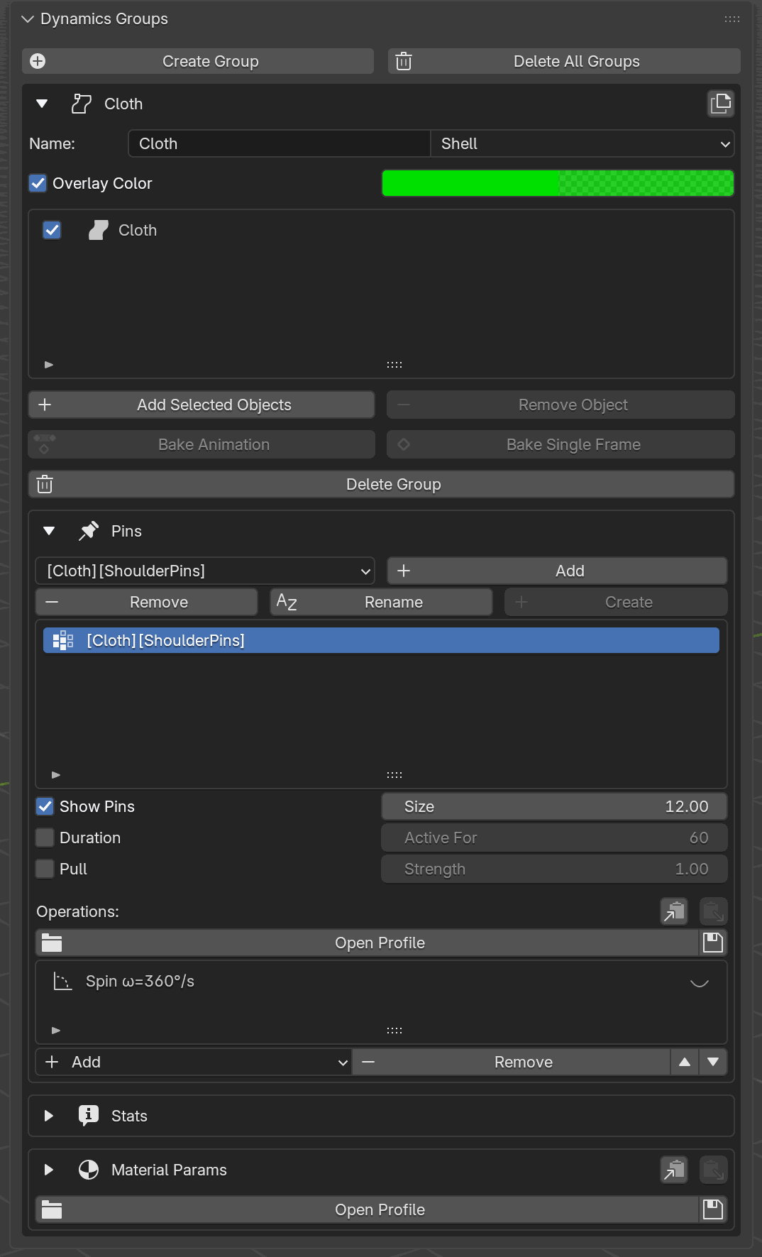
The Pins section of a group box, expanded. The [Cloth][ShoulderPins]
vertex-group selector, Add / Remove / Rename / Create buttons, the
pin UIList with the registered ShoulderPins entry, the pin-level
fields (Show Pins, Duration, Pull), and the Operations
list containing the Spin ω=360°/s operation row are all visible.
There are two UI paths to create a pin, both driven from the action buttons above the pin UIList:
From an existing vertex group. Use the left dropdown to pick the mesh object, then the right dropdown to pick the vertex group. Click Add Pin VG. The vertex group appears immediately as a new row in the pin UIList with its included checkbox on. This path is mesh-only, since curves have no vertex groups to pick from.
From an Edit-mode selection. Enter Edit Mode on a mesh or curve that belongs to this group, select the vertices (or curve control points) you want pinned, and click Create Pin VG. The add-on creates a new group from the current selection (naming it automatically), registers it as a pin with its Include checkbox on, and the new entry appears in the UIList. For meshes this writes a regular Blender vertex group; for curves it writes the internal
_pin_<name>custom property described above. This is the only way to create a pin on a curve object.
Remove deletes the currently-selected pin, including every operation attached to it. After removal, the selection moves to the next pin in the list, or the list becomes empty.
The Selected-Pin Details Panel
Selecting a pin in the UIList reveals a details panel below the list with the pin’s own properties:
Duration: a checkbox that enables an Active For frame field beside it. When on, the pin is released at that frame.
Pull: a checkbox with a Strength field next to it. When on, the pin no longer hard-constrains the vertices; instead, it pulls them toward their target positions as a soft force of the given strength.
Operations UIList: a list of the operations stacked on this pin, each row showing the operation type.
Pull is mutually exclusive with movement operations, since the solver would have no target to pull toward. The UI reflects this by disabling incompatible controls.
Adding an Operation
Below the Operations UIList in the selected-pin details panel are buttons arranged in two rows. The top row holds an Operations: label alongside Copy and Paste clipboard icons (copy the pin’s operation list to a session-scoped clipboard; paste replaces the target pin’s operations wholesale). The bottom row holds:
Add: opens a dropdown menu listing the available operation types (see below). New operations insert at the top of the list.
Remove: deletes the currently-selected operation. Removing an Embedded Move row is equivalent to Delete All Keyframes.
Up / Down triangles (▲ / ▼): reorder the selected operation within the list. Order determines the sequence in which the solver applies each operation’s contribution when more than one is stacked on the same pin.
The Add dropdown lists the available operation types:
Move By: translate the pinned vertices by a delta.
Spin: rotate the pinned vertices around an axis through a pivot.
Scale: scale the pinned vertices uniformly from a pivot.
Torque: apply a rotational force around a PCA-derived axis.
Embedded Move is not in the dropdown: it’s attached automatically on the first Make Keyframe press. Entries that would violate compatibility rules (e.g. adding Spin when a Torque already exists) are grayed out in the dropdown so you cannot select them.
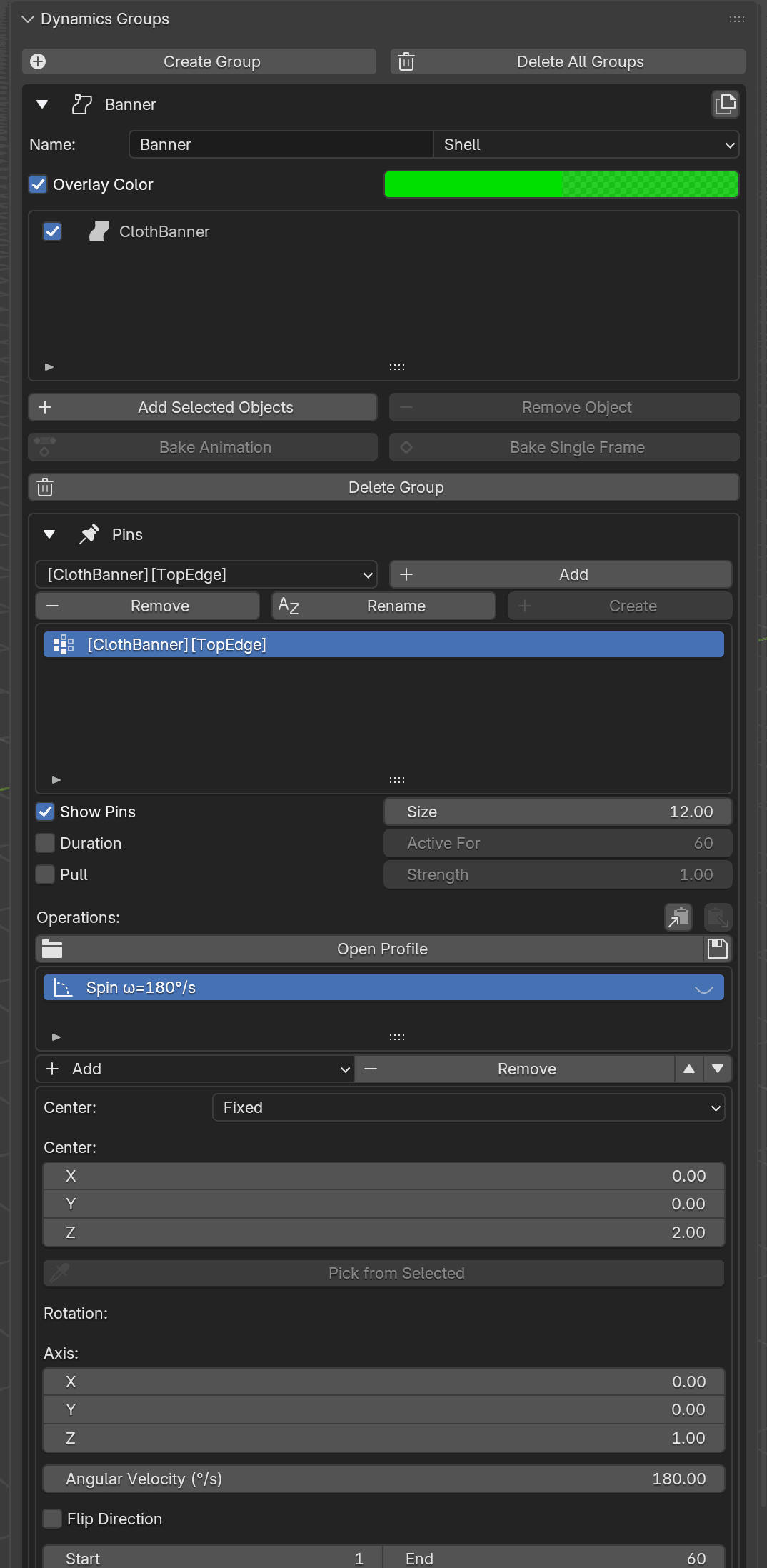
The selected-pin details panel on a Shell group. The four action buttons (Add / Remove / Rename / Create) sit above the pin list. Above the Operations list are the Copy / Paste clipboard icons; below it are Add, Remove, and the ▲ / ▼ reorder triangles. A Spin operation is selected with Center set to Fixed, which exposes the XYZ coordinate fields and the Pick from Selected eyedropper.
Picking an entry inserts a new operation row into the pin’s Operations UIList. Each row in that list shows:
The operation type label (e.g. Spin, Move By).
A small overlay-visibility toggle (eye icon) on the right side of the row. Clicking it turns the viewport overlay for that operation on or off, useful for previewing pivots or directions without running the solver.
Clicking an operation row selects it and opens the per-operation editor directly below the operations list. The fields shown depend on the operation type:
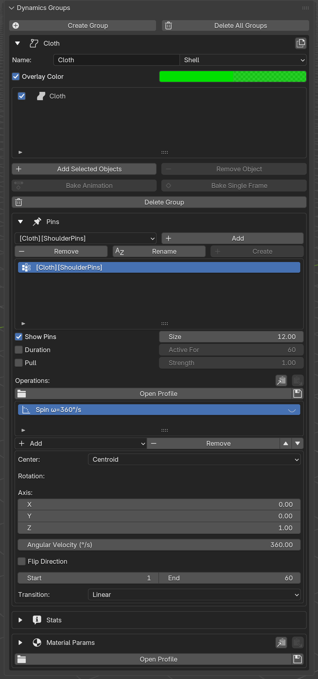
The selected-pin details panel with the Spin ω=360°/s operation
selected in the Operations UIList. Its per-type editor is visible
below: the Center dropdown (set to Centroid), the Axis XYZ
vector, Angular Velocity (°/s), Flip Direction toggle, Start
/ End frame range, and the Transition dropdown.
Move By: Delta (m) (XYZ vector), Start, End, Transition dropdown (Linear / Smooth).
Spin: Axis (XYZ vector), Angular Velocity (°/s), a Center dropdown (see below), the center-mode’s companion field, Start, End, Transition.
Scale: Factor (scalar), a Center dropdown + companion field, Start, End, Transition.
Torque: Magnitude (N·m), Axis dropdown (PC1 / PC2 / PC3), Flip Direction checkbox, Start, End.
Embedded Move: no editable fields; this operation is managed entirely via the Make Keyframe and Delete All Keyframes buttons (see below).
Warning
Torque cannot coexist with Move By, Spin, or Scale on the same pin. It can coexist with Embedded Move. The Add dropdown enforces this at creation time; incompatible entries are grayed out.
Make Keyframe
The Make Keyframe button appears in the edit-mode row (see above) and drives the Embedded Move operation. On the first press for a given pin:
It samples the current positions of the pinned vertices at the current scene frame.
It attaches an Embedded Move operation to the pin and stores the samples as its first keyframe.
Subsequent presses add more keyframes at the current scene frame without duplicating the operation; only one Embedded Move ever exists per pin. Visibly, each press “bakes in” the current posed shape of the pinned vertices; scrubbing the timeline then plays back the keyframes as the simulation runs.
Delete All Keyframes removes every keyframe and the Embedded Move operation in one step.
Capture Deformation
When the pinned vertices already follow a deformer on the cloth mesh, such as an Armature pose, a Lattice cage, a Mesh Deform cage, animated Shape Keys, or a driver, pressing Make Keyframe at every frame to mirror the motion is impractical. Capture Deformation does the sampling pass for you.
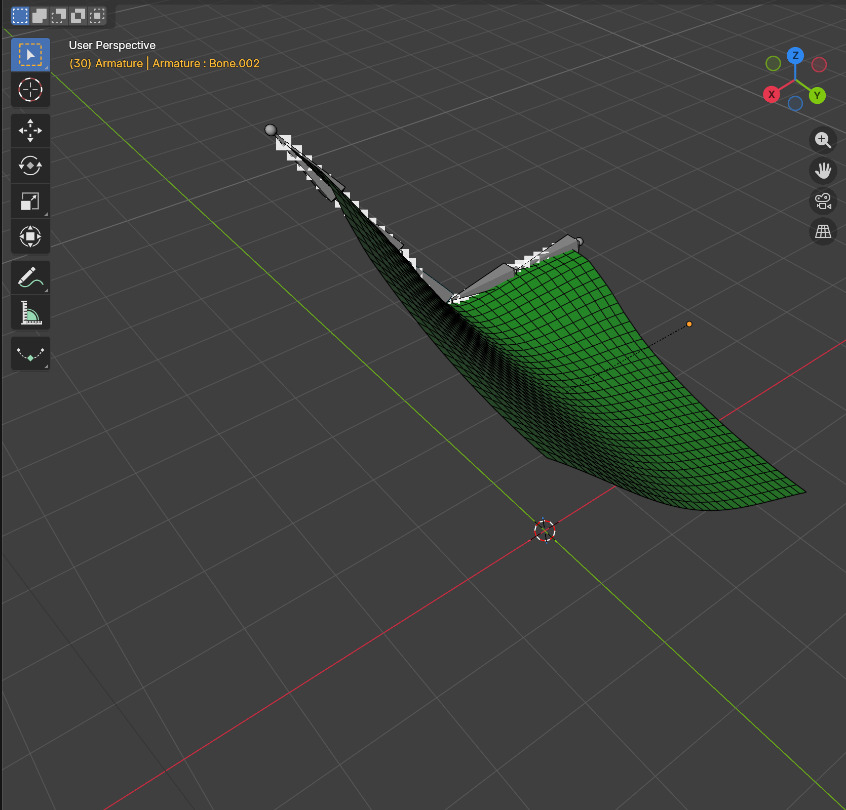
A cloth driven by a multi-bone armature partway through its pose animation. The white pin overlay dots follow the bone-driven edge, so the solver sees the pin’s target position at every frame without any per-frame keyframing by the artist.
Where the controls live
In the Pins section of the pin’s group, with the pin selected in the
list, two buttons appear under the Show Pins row: Capture
Deformation and Clear Deformation Cache. Both turn on only when
the pin’s mesh has a deforming modifier on it. When a cache exists, a
Pin cache: N frame(s) label sits just below the buttons, and the
operation list shows an [Embedded] Move (Captured) entry that
labels the captured animation as the live source.
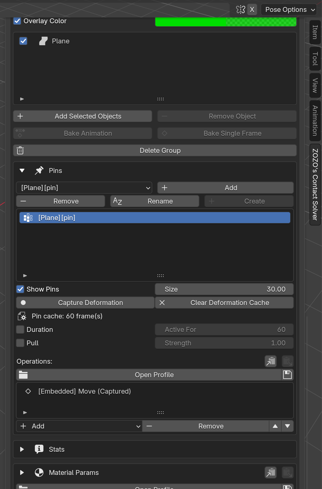
The same pin’s section in the Dynamics Groups panel. The captured
state is visible in three places at once: the Capture Deformation
/ Clear Deformation Cache row, the Pin cache: 60 frame(s)
status line, and the [Embedded] Move (Captured) entry in
Operations.
Using it
Bind the cloth to its deformer the usual way (e.g. parent to the armature and add an Armature modifier; pose the bones and keyframe the pose).
Create the Dynamics Group, add the cloth, and register the pin vertex group on the edge or region you want the bones to drive.
Set the scene frame range to cover the pose animation, then press Capture Deformation. A progress label reports as it walks the range; on completion the Pin cache count appears and the operation row updates.
Press Transfer and Run as usual. The pinned vertices follow the bones; the rest of the cloth simulates around them.
Press Capture Deformation again any time the underlying animation changes, a new pose, edited keys, a different modifier; the cache does not refresh on its own.
Clear Deformation Cache discards the cache and returns the pin to
its previous state. If the pin had no manual Make Keyframe
authoring underneath, the [Embedded] Move entry is removed too.
Note
Capture Deformation and manual Make Keyframe authoring cannot co-exist on the same pin. Capture refuses to start while manual keyframes are present (press Delete All Keyframes first), and Make Keyframe refuses to add new keys to a captured pin (press Clear Deformation Cache first). Torque is also incompatible with captured animation, matching the existing Torque vs Embedded Move rule.
Under the hood
Capture writes a per-pin cache keyed by the cloth object and the vertex group name; reopening the file on a host where the cache file is missing automatically clears the captured marker so the pin won’t silently feed stale data into the next Transfer.
When the cloth has a deformer on it, the solver-output cache modifier is installed after the deformer in the modifier stack. This avoids re-applying the bone displacement on top of the solver’s already bone-aware output, which would visibly double the motion on playback.
Center-Mode Dropdown and Overlays
Spin and Scale both rotate or scale around something. The per-operation editor exposes that “something” as a Center dropdown with four modes, each revealing a different companion field underneath:
Mode |
Companion field |
How the pivot is resolved |
|---|---|---|
Centroid |
(none) |
Mean of the pinned vertex positions. |
Fixed |
XYZ coordinate + Pick from Selected eyedropper |
Fixed world-space point. With the mesh in Edit Mode and one or more vertices selected, the eyedropper writes the selection’s world-space centroid into the XYZ field. |
Max Towards |
Unit direction vector |
Centroid of the vertices furthest in that direction. |
Vertex |
Vertex index + Pick Vertex eyedropper |
A single vertex on the mesh. The eyedropper reads the one selected vertex in Edit Mode; it reports an error if zero or more than one vertex is selected. The pivot deforms with the mesh. |
Alongside each operation are viewport-overlay toggles (Show Max Towards, Show Vertex, and siblings) that draw the computed pivot in the viewport so you can preview it before solving.
A Wind-Blown Banner
A minimal end-to-end scene that exercises the pin system: a vertical cloth banner with its top edge pinned, deformed by wind.
Build the banner. Add a flat Plane, apply a Simple subdivision at Viewport level 5 (→ a 33×33 grid of vertices, i.e. 32 quads per side), then rotate it 90° around X and apply the rotation so it stands upright in the XZ plane.
Create the pin vertex group. Enter Edit Mode, select the top row of vertices (the 33 with the maximum Z), and create a new vertex group named TopEdge.
Register with a SHELL group. Leave Edit Mode, open the Dynamics Groups panel, click Create Group, set the type to Shell, then add the plane via Add Selected Objects.
Pin the top edge. In the group’s Pins section, pick
[ClothBanner][TopEdge]in the vertex-group selector and click Add Pin VG. Make sure Show Pins is on (it is by default) so the pinned vertices render as white dots in the viewport. Steps 3 and 4 leave the Dynamics Groups panel looking like this: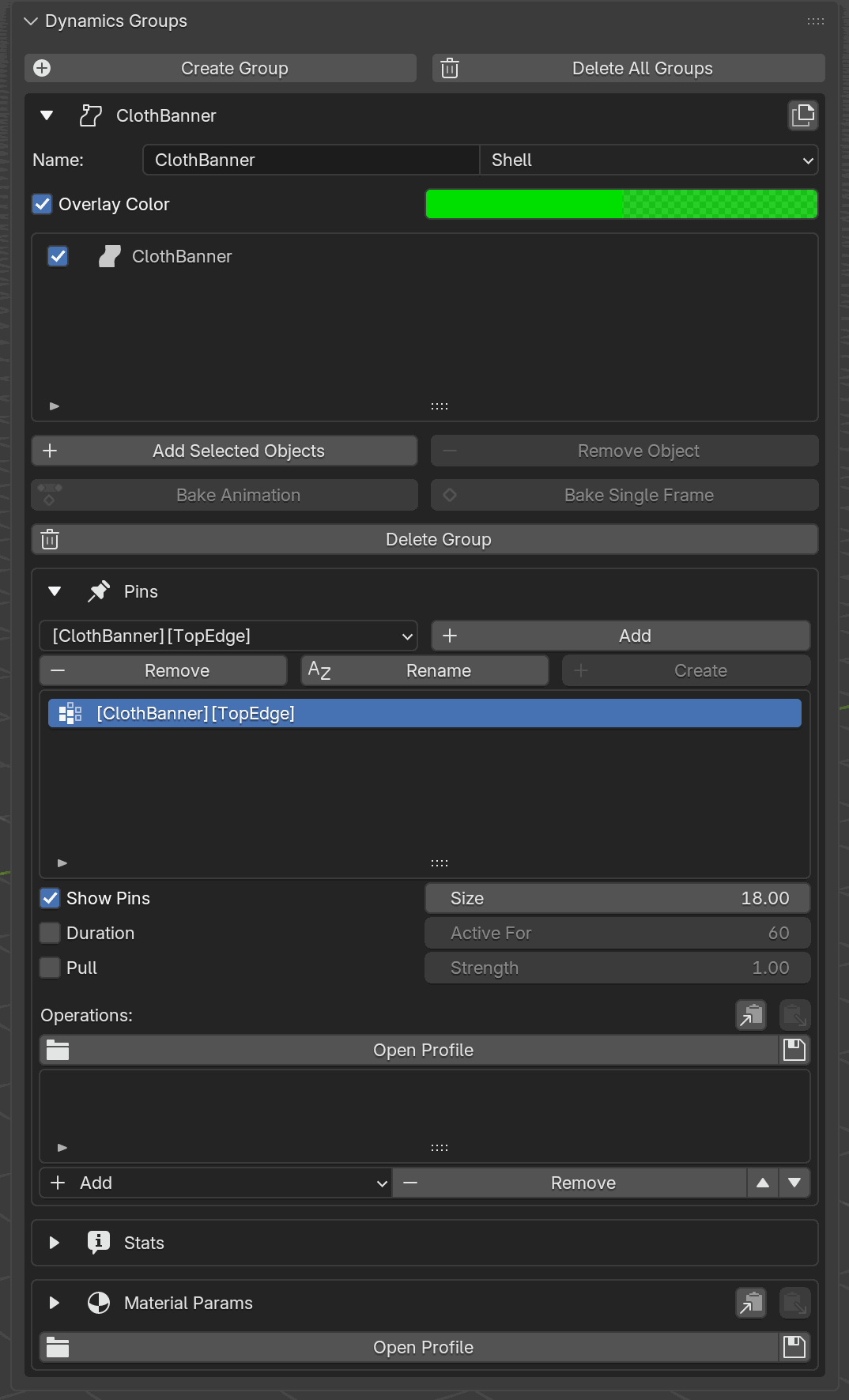
The panel after steps 3 and 4.
ClothBanneris the lone assigned object under the Shell group;[ClothBanner][TopEdge]is selected in the Pins list; Show Pins is on, Size is 18.¶Drive the wind. In the Scene Configuration panel, set the Wind direction to
(0, 1, 0)and Strength to around 20 m/s, then bump Air Density to0.01 kg/m³(the max). The force on the cloth scales with air density, so the default0.001 kg/m³leaves the banner barely moving.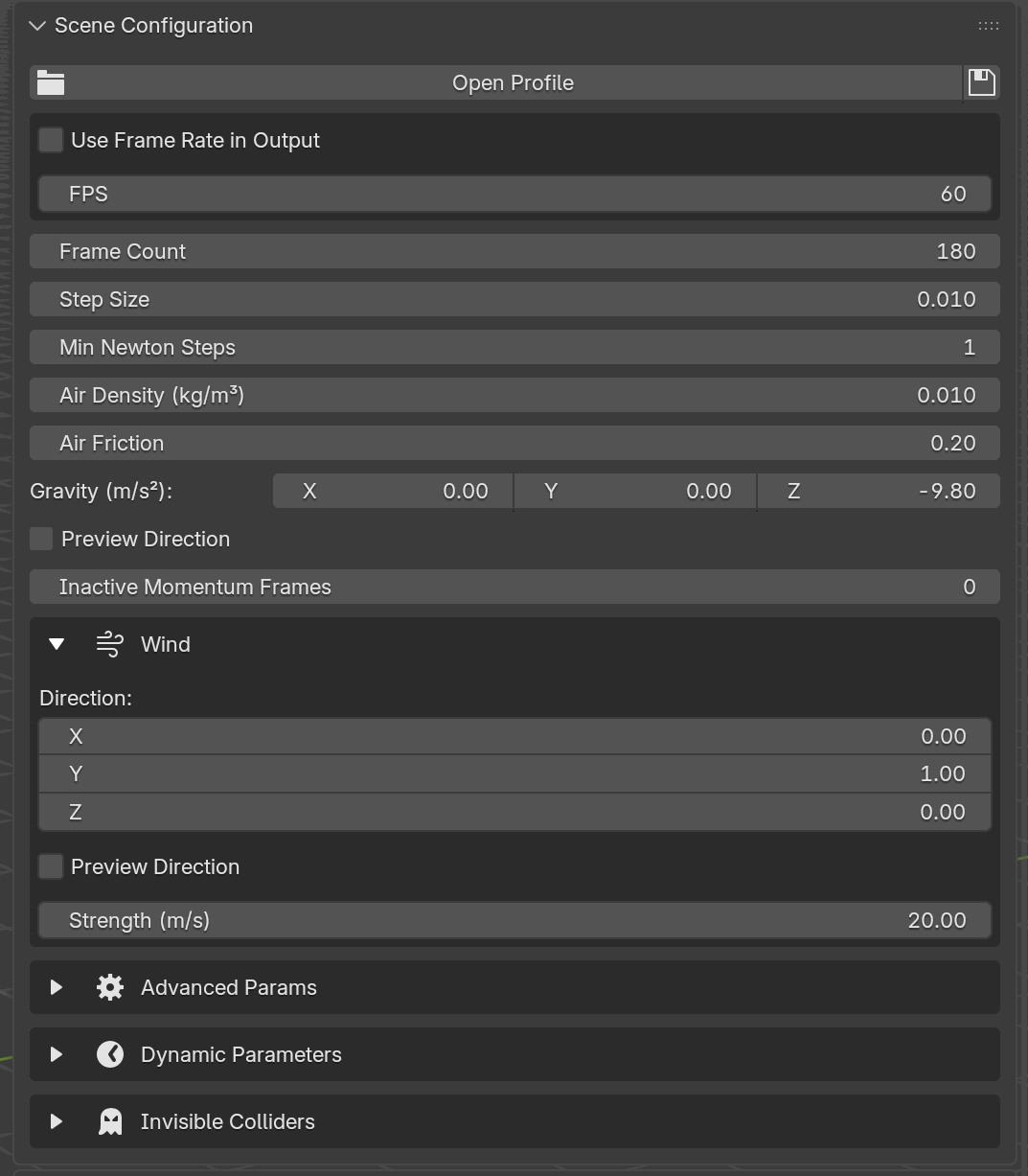
The matching Scene Configuration panel. Air Density is bumped to
0.01; the Wind sub-section is expanded with direction(0, 1, 0)and strength20.00 m/s.¶Transfer → Run.
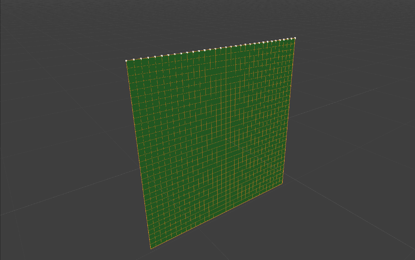
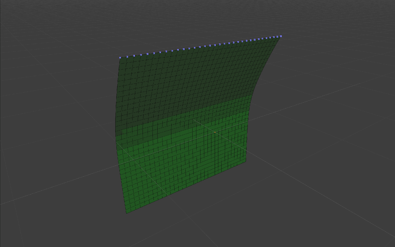
Rest pose at frame 1. The row of white dots along the top edge is the
Show Pins overlay drawing each vertex of TopEdge. Those vertices
are the ones the solver will hold fixed.
The same scene at frame 15, a fraction of a second after Run. The pinned vertices along the top, still marked by the overlay dots, have not moved at all; the rest of the cloth has bowed cleanly out in the wind direction.
Rest Shape and Pinning Every Vertex
When a pin covers every vertex of an object and a movement operation
(Move By, Spin, Scale, or Embedded Move) drives it, the
object’s rest shape is carried along by the pin: the solver treats the
transformed positions as the new rest configuration rather than trying
to restore the original pose. If the pin is later released via
Duration / Active For (or pin.unpin(frame=...)), the
simulation continues from the deformed shape as its rest pose; vertices
do not snap back to where they started. This is how you “pose” a garment
into a new resting configuration before letting it fall freely.
Pin Properties Reference
UI label |
Python / TOML key |
Description |
|---|---|---|
Include |
|
Pin is active for the current solve. |
Duration / Active For |
|
Release the pin at the given frame ( |
Pull / Strength |
|
Replace the hard pin with a soft pull force. |
Operations Reference
UI label |
Python / TOML key |
Parameters (UI labels) |
Description |
|---|---|---|---|
Embedded Move |
|
N/A |
Plays back per-vertex animation. Auto-added on first Make Keyframe (manual) or Capture Deformation (shown as |
Move By |
|
Delta (m), Start, End, Transition |
Translate the pinned vertices by a delta over a frame range. |
Spin |
|
Axis, Angular Velocity (°/s), Center, Start, End, Transition |
Rotate the pinned vertices around an axis through a pivot. |
Scale |
|
Factor, Center, Start, End, Transition |
Scale the pinned vertices uniformly from a pivot. |
Torque |
|
Magnitude (N·m), Axis (PC1/PC2/PC3), Flip Direction, Start, End |
Apply a rotational force around a PCA-derived axis. |
Transition is either Linear or Smooth between the operation’s Start and End frames.
The Spin and Scale rows use the Center fields from the table
above; under the hood their fields on each operation are spin_center*
for spin and scale_center* for scale, with identical suffixes:
*_center_mode: the mode enum (Centroid / Fixed / Max Towards / Vertex).*_center: the XYZ used by Fixed.*_center_direction: the direction used by Max Towards.*_center_vertex: the vertex index used by Vertex.
Blender Python API
The Python API mirrors the UI: you create a pin by vertex-group name and
chain operations onto it. All operation factories accept frame_start,
frame_end, and transition keywords; spin() and scale() accept the
center-mode inputs by keyword.
from bl_ext.user_default.ppf_contact_solver.ops.api import solver

cloth = solver.create_group("Cloth", "SHELL")
cloth.add("Shirt")

# A plain pin: vertices stay fixed.
shoulder = cloth.create_pin("Shirt", "ShoulderPins")

# Rotate the collar around world-Z for the first second.
collar = cloth.create_pin("Shirt", "CollarPins")
collar.spin(axis=[0, 0, 1], angular_velocity=360, frame_start=1, frame_end=60)

# Shrink the hem from its top edge, smoothly.
hem = cloth.create_pin("Shirt", "HemPins")
hem.scale(
    factor=0.5,
    center_direction=(0, 0, -1),   # MAX_TOWARDS: pivot = lowest verts
    frame_start=1, frame_end=60,
    transition="SMOOTH",
)

# Release a pin after 90 frames.
shoulder.unpin(frame=90)

# Translate the pinned vertices by a fixed offset, ramped over a frame
# range. (The interactive keyframed move, EMBEDDED_MOVE, is UI-only; the
# Python API exposes move_by instead.)
sleeve = cloth.create_pin("Shirt", "SleevePins")
sleeve.move_by(delta=(0, 0, 0.5), frame_start=20, frame_end=30, transition="SMOOTH")
sleeve.unpin(frame=60)

# Torque cannot be mixed with MOVE_BY, SPIN, or SCALE on the same pin.
twist = cloth.create_pin("Shirt", "TwistPins")
twist.torque(magnitude=1.0, axis_component="PC3", frame_start=1, frame_end=60)
Center-Mode Inference
spin() and scale() pick the center mode for you based on which kwarg
you pass:
Kwarg provided |
Mode resolved |
|---|---|
|
|
|
|
|
|
(none) |
|
Pass center_mode= explicitly if you want to override.