🧪 Material Parameters
Every object group carries its own copy of the full material-parameter set, but which fields are relevant depends on the group’s type:
Shell: density, stiffness (Young’s modulus, Poisson ratio, bend), shrink, strain limit, inflate, stitch, and contact settings.
Solid: density, stiffness, a single shrink factor, and contact settings.
Rod: density, stiffness, bend, strain limit, and contact settings.
PDRD: density, friction, and contact settings only. PDRD is an exactly-rigid body type with no Young’s modulus, Poisson ratio, bend, shrink, strain limit, or inflate.
Static: only friction and contact settings (static objects have no deformation to tune). See Static Objects for the full treatment of Static groups, including how to animate them.
Sand: a granular body whose relevant fields are grain radius, particle mass, friction, and contact settings.
Rows that don’t apply to the current type are hidden in the UI.
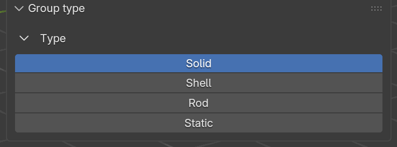
The six options in the group-type dropdown on each group’s header row. Picking one changes the Material Params box to match: Solid shows density, stiffness, and a single shrink factor; Shell shows the full cloth stack including anisotropic shrink, strain limit, inflate, and stitch; Rod shows density, stiffness, bend, and strain limit; Static collapses to just Friction and the contact rows; and Sand shows grain radius, particle mass, friction, and the contact rows.
The Material Params Box
At the bottom of each group card in the Dynamics Groups panel is a collapsible Material Params box. When you expand it you see a type-specific set of parameter rows: switching the group’s type (for example from Solid to Shell) immediately changes which rows are visible, so the box always reflects the parameters that actually affect the selected type. A Static group shows only the Friction and Contact rows; a Shell group shows the full stack of density, stiffness, bending, shrink, strain limit, inflation, and stitch fields; and so on.
The rows you see inside Material Params, top to bottom:
Model (when applicable): dropdown to pick the material model. Shell groups can choose Baraff-Witkin or ARAP; Solid groups pick between Stable NeoHookean and ARAP; Rod groups are locked to ARAP; Static groups have no model row. Older
.blendfiles that stored Stable NeoHookean on a Shell group still load: theshell_modelenum keeps the slot for.blendindex stability and the transfer step coerces that selection to ARAP at encode time.Density: the material’s density in type-appropriate units (kg/m² for Shell, kg/m³ for Solid, kg/m for Rod).
Young’s Modulus: stiffness. See the note below for how the solver interprets it.
Poisson Ratio: for Shell and Solid only.
Friction: Coulomb friction coefficient at contacts.
Bend stiffness and Shrink. Shell shows Bend, Shrink X/Y, a Strain Limit toggle, an Inflate toggle, and a Stitch Stiffness field. Solid collapses down to a single Shrink slider. Rod reuses the Shell Bend row.
Contact Gap: a toggle picks between absolute distance (in Blender units) and a fraction of the group’s bounding-box diagonal; the relevant pair of fields shows up below the toggle.
Collision Active Duration Windows: optional per-object frame ranges that restrict when contact is active. Off by default for Solid, Shell, and Rod groups; unavailable for Static. Covered in Active collision windows.
Plasticity: optional non-linear permanent deformation. Covered in its own subsection below.
Velocity Overwrite: optional keyframed velocity targets for one of the assigned objects. Covered separately below.
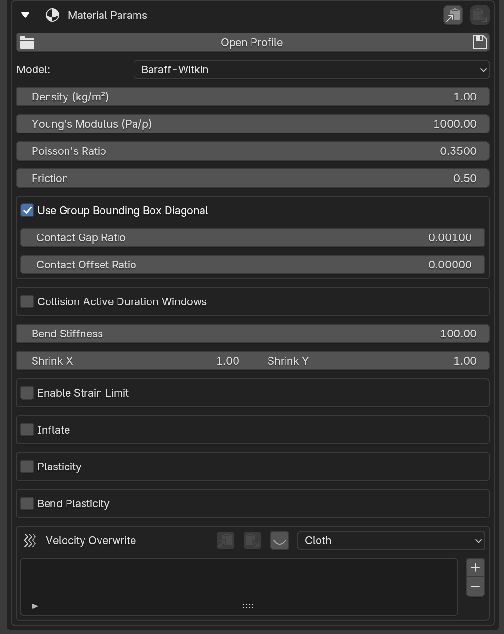
The Material Params box expanded on a Shell group. The exact row set changes with the group’s type: Solid collapses Shrink X/Y into a single Shrink, Rod drops Poisson ratio, and Static hides everything except Friction and the contact rows.
Profile Buttons: Open / Clear / Reload / Save
Along the header of the Material Params box are four small buttons that operate on a material profile (a TOML file listing named parameter presets):
Open: pops a file picker and loads the selected TOML into the profile dropdown for this group. The dropdown then lists every entry in the file; picking one pushes its parameters into the group.
Clear: forgets the loaded file. The dropdown disappears until you open another TOML.
Reload: re-reads the currently loaded TOML from disk and re-applies the active preset.
Save: writes the group’s current parameters back into the loaded TOML under a chosen entry name, replacing the existing entry if the name already exists.
Before a profile is loaded, the row collapses to a single Open Profile button plus the Save icon (save can write a brand-new TOML without an existing one). Once a profile is loaded, the Profile dropdown appears and all four icons line up to the right of it.
Important
Material-profile TOML files are created by the Save icon, not by
hand. Tune the group’s material parameters in the panel, click the
Save icon, name the entry, and the add-on writes (or overwrites) it
in the .toml for you. The TOML structure documented below is shown
for inspection and sharing only; the supported edit path is always UI →
Save.
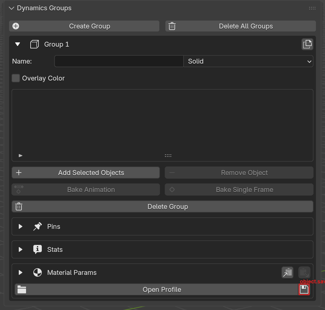
The per-group Save icon (floppy disk, highlighted in red) at the
top-right of the Material Params profile row. Click it to write the
group’s current material-parameter values to a .toml file, creating
the file on first save and overwriting the currently selected entry
afterwards.
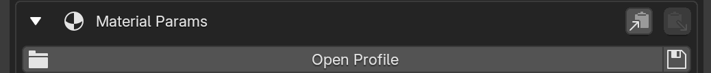
Before loading a profile. The row shows a full-width Open Profile button on the left and the save icon on the right. The Copy / Paste clipboard icons sit at the top-right of the Material Params header for moving parameters between groups in the same session.
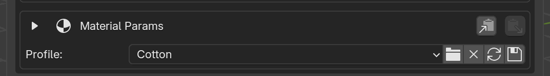
After loading a profile. The Profile dropdown (here set to
Cotton) now lists every entry in the loaded TOML; the four icons to
its right are Open, Clear, Reload, Save, left to
right.
Copy / Paste
Next to the profile buttons is a pair of Copy and Paste buttons. Copy snapshots every field in the current group’s material parameters to an internal clipboard; Paste applies that clipboard to another group. This is the fastest way to reuse a tuned material without writing a TOML file, but the clipboard lives only for the current Blender session.
Rayleigh Damping
Solid, Shell, and Rod groups expose stiffness-proportional
Rayleigh damping in a Rayleigh Damping box. Both coefficients default
to 0.0 (no damping), must be non-negative, and are measured in seconds.
UI label |
Python / TOML key |
Default |
Applies to |
Description |
|---|---|---|---|---|
Deformation Damping |
|
0.0 |
Solid, Shell, Rod |
Damps stretch / membrane / solid deformation (seconds). |
Bending Damping |
|
0.0 |
Shell, Rod only |
Damps shell and rod bending (seconds). Solid has no bending term. |
Start near zero and raise these only to calm jitter. Small values (roughly 0.001 – 0.01 s) already reduce visible jitter noticeably; bending damping is usually smaller than deformation damping.
Note
PDRD groups are not Rayleigh-damped. The damping coefficients apply to the FEM element types (Solid, Shell, Rod) only.
Under the hood
Stiffness-proportional damping adds a (beta/dt) * K term to the system,
where K is the element tangent stiffness and beta is the coefficient
in seconds. The deformation term reuses the SPD-projected deformation
Hessian; the bending term uses a lagged-dihedral form so it stays
dissipative. Tetrahedral (Solid) elements use only the deformation term,
since a tet has no bending energy.
Shell-Specific
UI label |
Python / TOML key |
Default |
Description |
|---|---|---|---|
Model |
|
|
Material model. One of |
Density (kg/m²) |
|
1.0 |
Areal density, kg/m². |
Young’s Modulus (Pa/ρ) |
|
1000.0 |
Young’s modulus (see note below). Accepted range 0 – 10 M. |
Poisson’s Ratio |
|
0.35 |
Poisson ratio, 0 – 0.4999. |
Bend Stiffness |
|
10.0 |
Bending stiffness. Min 0, soft max 100. |
Shrink X |
|
1.0 |
Anisotropic warp scale (min 0.1). < 1 shrinks, > 1 extends. |
Shrink Y |
|
1.0 |
Anisotropic weft scale (min 0.1). < 1 shrinks, > 1 extends. |
Enable Strain Limit |
|
|
Turns on non-physical strain clamp (good for stiff cloth). |
Strain Limit |
|
5.0 |
Max stretch beyond rest length, as a percentage (5.0 = 5%). Active only when Enable Strain Limit is on. |
Inflate |
|
|
Turns on per-face pressure along face normals. |
Pressure (Pa) |
|
0.0 |
Inflation pressure, Pa. Active only when Inflate is on. |
Stitch Stiffness |
|
1.0 |
Stiffness of loose-edge stitches detected in the mesh. |
Loose edges (edges not belonging to any face) are automatically treated as stitch constraints, with stiffness set by Stitch Stiffness.
Shrink X / Shrink Y
What it does: anisotropic rest-shape scale. Shrink X scales the warp direction and Shrink Y the weft; values below 1 shrink the cloth along that axis, values above 1 extend it. They act on the rest shape, so the solver sees the stretched/shrunk target as the relaxed configuration and drives the mesh toward it under the usual stiffness.
When to enable: use to bake in pre-tension (shrink to pull seams taut),
to inflate panels slightly, or to recover the target shape after mesh
sewing. Leave both at 1.0 when you want the mesh drawn in Blender to
be the rest shape.
Example values:
(1.0, 1.0): default; no anisotropic rescale.(0.95, 0.95): ~5% uniform shrink (mild curl / gathers).(0.9, 1.1): shrink warp, extend weft (asymmetric tension).
Note: enabling shrink/extend disables Strain Limit for the same group. The two systems fight, so the UI warns when both are active.
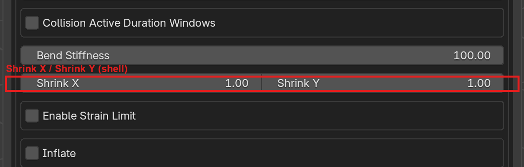
Shell groups expose Shrink X and Shrink Y on the same row. Each is a scale factor relative to the rest shape; 1.0 leaves the axis alone.
Strain Limit
Available on Shell and Rod groups (not Solid).
What it does: non-physical clamp that prevents mesh edges from stretching beyond the strain limit. Helpful for stiff cloth or ropes that look rubbery in a plain spring formulation.
When to enable: cloth that should keep its silhouette (denim, tablecloths, airbags) or ropes that must not visibly stretch. Disable when you want the mesh to deform freely under force, or when Shrink X / Shrink Y are non-unity on a Shell group (the two systems conflict).
Example values:
Strain Limit = 2.5%: very stiff (~2.5% stretch).
Strain Limit = 5%: default; tight but drapes visibly.
Strain Limit = 15%: loose; bigger ripples.
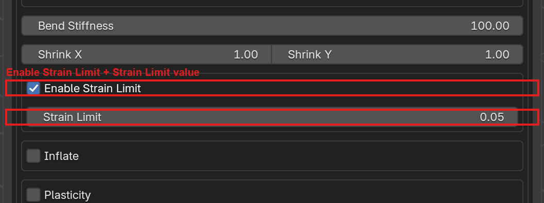
With Enable Strain Limit on, the Strain Limit field activates. The value is a stretch percentage (5% means edges may stretch 5% beyond rest length), not a force.
Inflate
What it does: applies a per-face pressure along each face normal, pushing the mesh outward (or inward with negative values, once you dip below zero via the Python API). Acts uniformly over the surface like a balloon or airbag.
When to enable: inflatables (pillows, airbags, balloons), soft garments that need a puffy silhouette, or any shell that should resist collapse into a flat sheet. Leave off for ordinary cloth; gravity and bending already do the right thing.
Example values:
Pressure (Pa) = 0.0: default; feature is inert even when toggled on.
Pressure (Pa) = 1.0: gentle puff; subtle volume for a pillow.
Pressure (Pa) = 10.0: strong; airbag-style rapid fill.
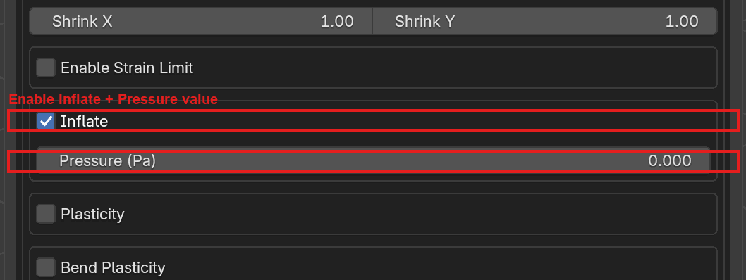
Enable Inflate exposes the Pressure (Pa) slider. The unit label is Pa but the solver applies it relative to density, like Young’s modulus (see the note below), so tune by eye rather than against SI values.
Plasticity
What it does: adds permanent deformation on top of the elastic response. When the local stretch exceeds the Threshold (a dead zone around zero strain), the rest shape drifts toward the current shape at a rate controlled by Theta. A matching Bend Plasticity section does the same for the bending energy, with its own theta and angular threshold.
When to enable: materials that remember their deformation, such as crushed foil, wrinkled paper, dented metal sheets, or sagging fabric. Keep off for perfectly elastic cloth.
Example values:
Theta = 0.0: disabled even if the checkbox is on.
Theta = 0.5: default; ~40%/s creep once over threshold.
Theta = 5.0: fast creep (~99%/s); nearly immediate set.
Threshold = 0.02: ignore strains below 2%.
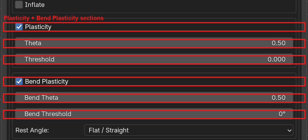
Shell groups expose two plasticity sections: Plasticity (stretch) and Bend Plasticity (hinge/rod-joint rest angle). Each has its own theta rate and threshold; bend plasticity also lets you pick the rest-angle source (Flat / Straight, or From Initial Geometry).
Velocity Overwrite
What it does: the bottom box in the Material Params stack. It stores a
per-object list of keyframed velocity vectors. Each entry pins the
whole group to a given (direction, speed) at a chosen frame, overriding
the velocity produced by the simulation. The dropdown on the header row
picks which assigned object receives the keyframes; the eye icon toggles
a viewport preview arrow; the copy/paste icons move the keyframe list
between groups.
When to enable: scripted cloth launches (flag unfurling, parachute drops), matching reference motion on hero shots, or giving the solver a strong initial push that no constant velocity could time. Leave empty for fully passive simulations.
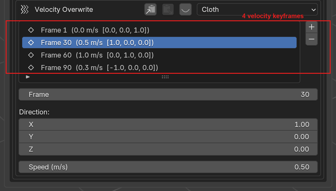
The Velocity Overwrite section with four keyframes populated
(frames 1, 30, 60, 90). Each row is frame (speed m/s [direction]).
The selected row expands into per-keyframe editor rows (Frame,
Direction (XYZ), and Speed) so you can tweak one entry
without opening an animation editor. The Cloth dropdown at the
top picks which assigned object the keyframes belong to, and the
+ / - buttons on the right add or remove entries.
Solid-Specific
UI label |
Python / TOML key |
Default |
Description |
|---|---|---|---|
Model |
|
|
Material model. Either |
Density (kg/m³) |
|
100.0 |
Volumetric density, kg/m³. |
Young’s Modulus (Pa/ρ) |
|
500.0 |
Young’s modulus (see note below). Range 0 – 10 M. |
Poisson’s Ratio |
|
0.35 |
Poisson ratio, 0 – 0.4999. |
Shrink |
|
1.0 |
Uniform rest-shape scale (min 0.1). |
Shrink
What it does: uniform (isotropic) rest-shape scale for the whole solid. The solver treats the shrunk / expanded shape as the relaxed target and drives the mesh toward it under the usual stiffness, so values below 1 visually contract the body and values above 1 swell it.
When to enable: pre-stressed solids (e.g. a rubber band that should
self-tension once the simulation starts), volumetric shrink after
tetrahedralization, or recovering a target volume after scale tweaks in
Blender. Leave at 1.0 for bodies that should rest exactly at their
modeled size.
Example values:
Shrink = 1.0: default; no rescale.
Shrink = 0.9: 10% shrink; body contracts and pulls on its neighbors.
Shrink = 1.05: 5% expansion; useful for “puffy” solids.
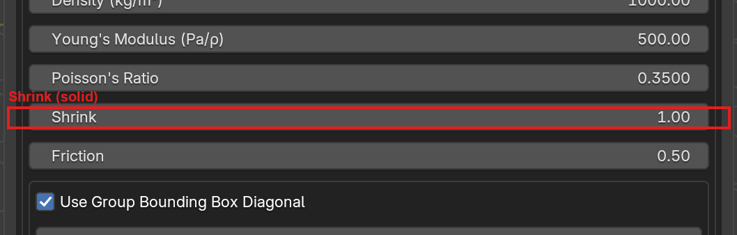
Solid groups expose a single Shrink row in the Material Params box (Shell groups instead get anisotropic Shrink X / Shrink Y).
Tetrahedralizer (per object)
Solid groups only. The bottom of the Material Params box on a Solid group has a Tetrahedralizer box. A solid’s surface is tetrahedralized before it is sent to the solver, and the box lets you pick how, per assigned object:
An Object dropdown on the header row picks which assigned mesh in the group you are configuring, so each solid in the group can use its own backend and overrides.
A backend dropdown below it chooses the tetrahedralizer:
fTetWild (the default): a tolerant remesher. It accepts open, cracked, or non-manifold input, but it resamples the surface, so your input vertices are reconstructed through a surface map rather than preserved exactly.
TetGen: surface-exact (a one-to-one vertex map). It requires a clean, closed, manifold mesh and rejects open, coplanar, or non-manifold input. If TetGen refuses a mesh, repair it, route the object to a Shell group, or switch it back to fTetWild.
The override rows below the backend dropdown change to match the selected backend.
fTetWild Overrides
When fTetWild is selected, six per-object overrides appear. Each row has an Override checkbox on the left and the value on the right; the value is only forwarded to fTetWild when its checkbox is on. With all overrides off, fTetWild runs at its own defaults.
UI label |
Python / TOML key |
Default |
Description |
|---|---|---|---|
Edge Length Factor |
|
0.05 |
Ideal tet edge length as a fraction of the bbox diagonal ( |
Epsilon |
|
0.001 |
Envelope size as a fraction of the bbox diagonal ( |
Stop Energy |
|
10.0 |
AMIPS energy threshold; larger = faster, lower quality. |
Max Opt Iterations |
|
80 |
Maximum fTetWild optimization passes. |
Optimize |
|
|
Improve cell quality (slower). |
Simplify Input |
|
|
Simplify the input surface before tetrahedralization. |
Coarsen Output |
|
|
Coarsen output while preserving quality. |
Each value has a matching ftetwild_override_<field> boolean that gates
whether the override is sent. Leave the box collapsed and untouched to
get the tetrahedralizer’s out-of-box behavior; reach for these only when
a solid is meshing too coarsely, missing features, or taking too long to
tetrahedralize.
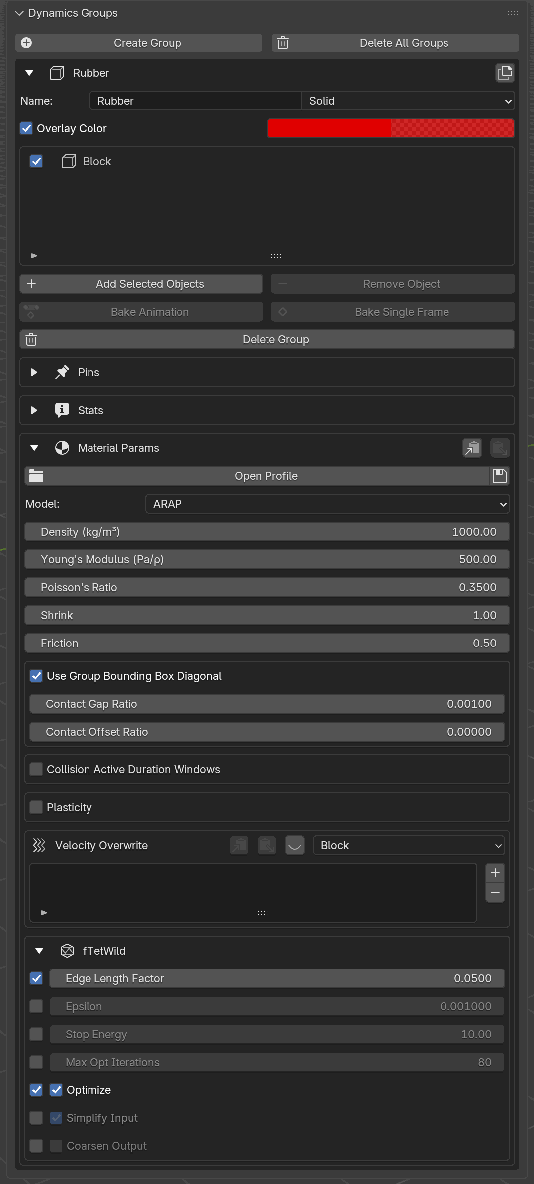
The fTetWild box expanded at the bottom of a Solid group’s Material Params. The left column is the per-field Override checkbox; with it off, the row is grayed and the tetrahedralizer’s own default is used. In this example Edge Length Factor and Optimize are overridden; the rest stay at defaults.
TetGen Overrides
When TetGen is selected, the override rows switch to TetGen’s interior controls. TetGen always preserves the input surface exactly, so these tune only the interior refinement. Each row uses the same Override checkbox pattern: the value is forwarded only when its box is on, and the rest of the time TetGen runs at its own defaults.
UI label |
Python / TOML key |
Default |
Description |
|---|---|---|---|
Min Radius-Edge Ratio |
|
2.0 |
Quality bound; smaller forces rounder interior cells ( |
Max Tet Volume |
|
0.0 |
Caps interior cell size in object units ( |
Rod-Specific
UI label |
Python / TOML key |
Default |
Description |
|---|---|---|---|
Model |
|
|
Material model. |
Density (kg/m) |
|
1.0 |
Line density, kg/m. |
Young’s Modulus (Pa/ρ) |
|
10000.0 |
Young’s modulus (see note below). |
Rod groups expose the same Bend Stiffness field as Shell;
it writes into the single bend property on the group, so both types
read and serialize it identically. Switching a group’s type to Rod
resets bend to 1.0 (the rod-tuned default); switching back to or
creating a Shell group leaves the global default of 10.0.
Rest Angle is exposed under Bend Plasticity for rods as well as shells: pick Flat / Straight to keep the analytic rest angle (shell hinge θ₀ = 0, rod θ₀ = π), or From Initial Geometry to take the rest angle from the input pose.
PDRD-Specific
PDRD (Painless Differentiable Rotation Dynamics) is an exactly-rigid body type. It exposes only density, friction, and contact settings. There is no Young’s modulus, Poisson ratio, bend, shrink, strain limit, or inflate, no rigidity or stiffness control (the body is exactly rigid, not a stiff penalty), and PDRD bodies are not tetrahedralized.
UI label |
Python / TOML key |
Default |
Description |
|---|---|---|---|
Density (kg/m³) |
|
100.0 |
Volumetric density, kg/m³. Mass is the density times the enclosed mesh volume. |
Density is the only material number a PDRD body exposes: it sets the mass (and, through the rest shape, the rotational inertia), which is what determines how the body responds to gravity, contact, and pins. The motion is exactly rigid at any mesh resolution, so there is no stiffness or rigidity value to tune.
Under the hood
Each PDRD body is solved in reduced 6-DOF coordinates (translation plus rotation): every Newton iteration fits the single best-fit rigid transform to the body and reconstructs its surface from that transform, so the body stays exactly rigid by construction rather than through a stiff penalty.
Hinge Joints
A PDRD body can be turned into a hinge: its position is pinned and its rotation is locked to a single principal (PCA) axis of its rest shape, so the body spins on that axis like a wheel on an axle. This is a per-object setting, so each body in one PDRD group can hinge on its own axle (for example, a train of gears that each turn on their own pin while tooth contact passes torque from one to the next).
The free axle is chosen by principal axis of the rest shape: 0 is
the largest extent, 1 the middle, and 2 the thinnest extent (the
usual axle for a flat gear or disk, and the default). From the Python API
a hinge is set per object with Group.set_hinge; from the MCP layer use
the set_pdrd_hinge tool. Pass enable=False to clear the hinge and let
the body move freely again.
from bl_ext.user_default.ppf_contact_solver.ops.api import solver

gears = solver.create_group("Gears", type="PDRD")
gears.add("GearA")
gears.set_hinge("GearA", pca_axis=2)   # spin on the thinnest axis
The hinge is a per-object property, not a group material attribute, so it does not appear in the Material Params table above.
Note
Young’s modulus behaves non-conventionally. The solver divides the
entered Young’s modulus by density internally. The practical effect is that
animated behavior is invariant to density alone: doubling density without
touching Young’s modulus produces the same motion (the mass doubles, but
the effective stiffness scales with it). This decouples “how heavy the
material is” from “how stiff it looks”, so you can tune stiffness and mass
independently. The example material presets in this guide (Cotton, Silk, Steel, …)
use physically meaningful values with that normalization in mind.
Density-Normalized (Pa/ρ)
Below the Young’s Modulus field on Shell, Solid, and Rod groups is a Density-Normalized (Pa/ρ) checkbox that sets what the number you type means.
UI label |
Python / TOML key |
Default |
Description |
|---|---|---|---|
Density-Normalized (Pa/ρ) |
|
|
On: Young’s modulus is the solver’s native Pa/ρ. Off: a true value in Pa. |
When it is on (the default), the Young’s modulus is a density-normalized value in Pa/ρ, the solver’s native convention: changing a body’s density alone leaves its motion unchanged, and the field label reads (Pa/ρ). Keep it on to match existing scenes and the example presets in this guide.
When you turn it off, you enter a true Young’s modulus in pascals (for example a value from a material reference table); the add-on divides it by this group’s density before sending it to the solver, so a denser body of the same material is correspondingly stiffer to move. The field label flips to (Pa) to show which convention is active.
Contact Gap and Contact Offset
Contact Gap and Contact Offset are two distances that together shape the invisible contact layer around each group’s geometry. They serve different roles and both are configurable.
Contact Gap is the barrier’s reach: the distance at which the solver starts applying a push-back force between two surfaces. A larger gap gives a softer, earlier-engaging barrier and costs more contact pairs; a smaller gap lets surfaces sit closer before the barrier kicks in. This is the setting most scenes need to tune.
Contact Offset is per-group padding added on top of the gap. At each contact check the solver sums the two participants’ offsets with the (averaged) gap and treats that total as the effective separation threshold. You can think of it as the group’s “skin thickness”: it guarantees a minimum clearance regardless of what the other side chose. The default is
0.0(no extra clearance), which is what most scenes want.
Reach for Contact Offset when one group needs a specific thickness for visual or collision reasons independent of what its neighbors do, for example a garment that should never touch the body by less than a millimeter no matter which body group it comes near. For day-to-day tuning of how tightly surfaces sit, leave Contact Offset at zero and adjust Contact Gap instead.
Contact Gap: Absolute vs Ratio
Both Contact Gap and Contact Offset can be specified in either of two ways:
Absolute (the Contact Gap and Contact Offset fields): a literal distance in Blender units. Good when you want a hard, known thickness, e.g. a 1 mm skin for a body.
Ratio (the Contact Gap Ratio and Contact Offset Ratio fields): a fraction of the group’s bounding-box diagonal, computed at transfer time. Good because it scales with the scene: rescaling a character by 10× doesn’t make the cloth penetrate.

The dashed red ring shows the contact-gap layer. Absolute mode keeps the layer thickness constant in world units, so it looks huge around a small object and thin around a large one. Ratio mode scales the layer with the object’s bounding box, so both look proportionally wrapped regardless of scale.
The Use Group Bounding Box Diagonal toggle picks between them. The default is ratio-of-bbox-diagonal because that’s what most users want; you only need to flip to absolute when the group contains unusually elongated objects (where the diagonal overestimates characteristic size) or when you need an exact contact thickness for matching against another group.
Both pairs (Contact Gap / Contact Gap Ratio and Contact Offset / Contact Offset Ratio) are independently controlled by the same toggle.
Material Profiles
A material profile is a named set of material parameters saved to a TOML file with the Save icon. A single file can hold any number of presets; profiles like these are easy to build:
Preset |
Type |
Notes |
|---|---|---|
|
Shell |
Light, stiff. Young = 100, density = 0.1 kg/m², strain limited. |
|
Shell |
Young = 50, density = 0.5 kg/m², bend = 0.5. |
|
Shell |
Soft, low-density, bend = 0.2, friction = 0.15. |
|
Shell |
Heavier, stiffer; full block of shell/solid/rod fields for hybrids. |
|
Solid |
Stable NeoHookean, density = 1100 kg/m³, friction = 0.8. |
|
Solid |
Stable NeoHookean, Young = 200 000, density = 7800 kg/m³. |
|
Rod |
Young = 10 000, density = 1.0 kg/m, bend = 1.0. |
|
Static |
Just a friction value, used for colliders. |
Note
Material profiles do not carry any object assignments, pin vertex groups, or per-object velocity overrides. They describe a material, not a scene.
Example TOML Stanza
The block below shows what the add-on writes out when you click Save. It is not a template to fill in by hand. Adjust a group’s Material Params in the panel and click the Save icon to produce (or update) a file like this.
The per-group Save icon (floppy disk, highlighted in red) on the
Material Params row. Clicking it writes the group’s current
material-parameter values to a .toml file, creating the file on the
first save and overwriting the currently selected entry afterwards.
[Cotton]
object_type = "SHELL"
shell_model = "BARAFF_WITKIN"
shell_density = 0.5
shell_young_modulus = 50.0
shell_poisson_ratio = 0.35
bend = 0.5
friction = 0.3

[Denim]
object_type = "SHELL"
solid_model = "ARAP"
shell_model = "BARAFF_WITKIN"
rod_model = "ARAP"
solid_density = 1000.0
shell_density = 0.8
rod_density = 1.0
solid_young_modulus = 500.0
shell_young_modulus = 200.0
rod_young_modulus = 10000.0
solid_poisson_ratio = 0.35
shell_poisson_ratio = 0.35
friction = 0.5
contact_gap = 0.001
contact_offset = 0.0
use_group_bounding_box_diagonal = true
contact_gap_rat = 0.001
contact_offset_rat = 0.0
bend = 2.0
shrink = 1.0
enable_strain_limit = true
strain_limit_percent = 5.0
stitch_stiffness = 1.0
Only the keys you include are applied; missing keys keep their current
value on the group. You don’t have to list every field for a preset to be
valid — a Static collider preset, for instance, can carry just a
friction value.
Blender Python API
The same workflow is available from Python. Every field in the
Material Params box is reachable through each group’s .param
attribute. Changes from Python appear in the panel immediately and vice
versa.
from bl_ext.user_default.ppf_contact_solver.ops.api import solver

cloth = solver.create_group("Cloth", "SHELL")
cloth.param.shell_density       = 0.5
cloth.param.shell_young_modulus = 50.0
cloth.param.friction            = 0.3
cloth.param.bend                = 0.5

# Solid body with Stable NeoHookean and a tighter contact skin.
body = solver.create_group("Body", "SOLID")
body.param.solid_density       = 1100.0
body.param.solid_young_modulus = 5000.0
body.param.use_group_bounding_box_diagonal = False
body.param.contact_gap         = 0.001

# Static collider: only friction and contact settings matter.
floor = solver.create_group("Floor", "STATIC")
floor.param.friction = 0.8
Under the hood
Loose-edge stitch encoding
At transfer time, edges on Shell meshes that are not adjacent to
any face are automatically emitted as stitch constraints with stiffness
set by stitch_stiffness. There is no UI surface for this; it happens
on every transfer.
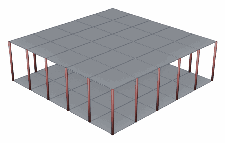
Two subdivided square Shell patches joined by vertical loose edges
(rendered here as red tubes). The patches are separate face regions;
the connecting edges belong to no face, so the transfer step emits each
one as a stitch constraint with stiffness stitch_stiffness.
Copy / Paste clipboard
The Copy / Paste buttons move parameters between groups within a
single Blender session. The clipboard is not persisted to the .blend
file, so restarting Blender clears it.